LIGHTING SYSTEM TERMINALS OF ECU

-
INSTRUMENT PANEL JUNCTION BLOCK (w/ Illuminated Entry System)
-
Disconnect the 5E, 5G, and 5M instrument panel junction block connectors.
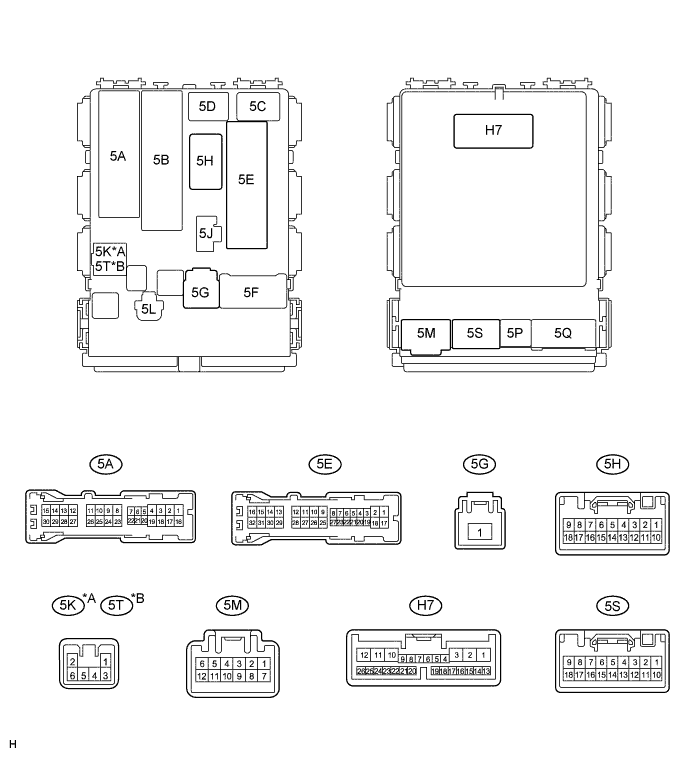
Text in Illustration *A for LHD *B for RHD -
Measure the voltage and resistance between the wire harness side connectors and body ground.
Voltage Symbols (Terminal No.) Wiring Color Terminal Description Condition Specified Condition +B (5G-1) - Body ground W - Body ground Battery power supply Always 11 to 14 V ECUB (5E-17) - Body ground W-R - Body ground Battery power supply Always 11 to 14 V Resistance Symbols (Terminal No.) Wiring Color Terminal Description Condition Specified Condition GND (5E-12) - Body ground W-B - Body ground Ground Always Below 1 Ω GND (5M-7) - Body ground W-B - Body ground Ground Always Below 1 Ω If the result is not as specified, there may be a malfunction on the wire harness side.
-
Reconnect the 5E, 5G, and 5M instrument panel junction block connectors.
-
Measure the resistance and voltage according to the value(s) in the table below.
Resistance Symbols (Terminal No.) Wiring Color Terminal Description Condition Specified Condition CLTE (H7-24) - GND (5E-12)*1 W - W-B Ground Always Below 1 Ω Voltage (for LHD) Symbols (Terminal No.) Wiring Color Terminal Description Condition Specified Condition RCTY (5A-9) - GND (5E-12) W - W-B*3
G - W-B*4
Back door courtesy switch signal Back door open Below 1 V RCTY (5A-9) - GND (5E-12) W - W-B*3
G - W-B*4
Back door courtesy switch signal Back door closed 11 to 14 V*7
Pulse generation*7
RCTY (5A-18) - GND (5E-12) W - W-B Rear door courtesy switch RH signal Rear door RH open Below 1 V RCTY (5A-18) - GND (5E-12) W - W-B Rear door courtesy switch RH signal Rear door RH closed 11 to 14 V*7
Pulse generation*7
RCTY (5A-30) - GND (5E-12)*2 W - W-B Rear door courtesy switch LH signal Rear door LH open Below 1 V RCTY (5A-30) - GND (5E-12)*2 W - W-B Rear door courtesy switch LH signal Rear door LH closed 11 to 14 V*7
Pulse generation*7
PCTY (5E-10) - GND (5E-12) R-L - W-B Front passenger side door courtesy switch signal Front passenger side door open Below 1 V PCTY (5E-10) - GND (5E-12) R-L - W-B Front passenger side door courtesy switch signal Front passenger side door closed 11 to 14 V*7
Pulse generation*7
DCTY (5E-27) - GND (5E-12) R-G - W-B Driver side door courtesy switch signal Driver side door open Below 1 V DCTY (5E-27) - GND (5E-12) R-G - W-B Driver side door courtesy switch signal Driver side door closed 11 to 14 V*7
Pulse generation*7
TRLY (5H-3) - GND (5E-12)*1 R - W-B Headlight dimmer switch signal Headlight dimmer switch OFF 11 to 14 V TRLY (5H-3) - GND (5E-12)*1 R - W-B Headlight dimmer switch signal Headlight dimmer switch AUTO Below 1 V LP (5H-5) - GND (5E-12) R-Y - W-B Ignition key cylinder light signal Ignition key cylinder light on using illuminated entry system Below 1 V LP (5H-5) - GND (5E-12) R-Y - W-B Ignition key cylinder light signal Ignition key cylinder light off using illuminated entry system 11 to 14 V LP (5K-2) - GND (5E-12) LG - W-B Interior light signal Interior light on using illuminated entry system Below 1 V LP (5K-2) - GND (5E-12) LG - W-B Interior light signal Interior light off using illuminated entry system 11 to 14 V AUTO (H7-10) - GND (5E-12)*1 BE - W-B Headlight dimmer switch signal Headlight dimmer switch OFF 11 to 14 V AUTO (H7-10) - GND (5E-12)*1 BE - W-B Headlight dimmer switch signal Headlight dimmer switch AUTO Below 1 V HRLY (H7-14) - GND (5E-12)*1 R-Y - W-B HEAD relay drive signal Headlight dimmer switch OFF 11 to 14 V HRLY (H7-14) - GND (5E-12)*1 R-Y - W-B HEAD relay drive signal Headlight dimmer switch AUTO (when headlights are on) Below 1 V LSWD (H7-20) - GND (5E-12) W - W-B Driver side door unlock detection switch signal Driver side door unlocked Below 1 V LSWD (H7-20) - GND (5E-12) W - W-B Driver side door unlock detection switch signal Driver side door locked 11 to 14 V*7
Pulse generation*7
CLTS (H7-25) - GND (5E-12)*1 B - W-B Automatic light control sensor signal Ignition switch OFF Below 1 V CLTS (H7-25) - GND (5E-12)*1 B - W-B Automatic light control sensor signal Ignition switch ON
Headlight dimmer switch AUTO
Pulse generation
(see waveform 1)
CLTB (H7-26) - GND (5E-12)*1 P - W-B Automatic light control sensor signal Always 11 to 14 V EHW (5S-17) - GND (5E-12) G-W - W-B Hazard warning switch signal Hazard warning switch OFF 11 to 14 V EHW (5S-17) - GND (5E-12) G-W - W-B Hazard warning switch signal Hazard warning switch ON Below 1 V Voltage (for RHD) Symbols (Terminal No.) Wiring Color Terminal Description Condition Specified Condition RCTY (5A-9) - GND (5E-12) W - W-B*3
G - W-B*4
Back door courtesy switch signal Back door open Below 1 V RCTY (5A-9) - GND (5E-12) W - W-B*3
G - W-B*4
Back door courtesy switch signal Back door closed 11 to 14 V*7
Pulse generation*7
RCTY (5A-18) - GND (5E-12)*2 W - W-B Rear door courtesy switch RH signal Rear door RH open Below 1 V RCTY (5A-18) - GND (5E-12)*2 W - W-B Rear door courtesy switch RH signal Rear door RH closed 11 to 14 V*7
Pulse generation*7
RCTY (5A-30) - GND (5E-12) W - W-B Rear door courtesy switch LH signal Rear door LH open Below 1 V RCTY (5A-30) - GND (5E-12) W - W-B Rear door courtesy switch LH signal Rear door LH closed 11 to 14 V*7
Pulse generation*7
PCTY (5E-10) - GND (5E-12) R-G - W-B Front passenger side door courtesy switch signal Front passenger side door open Below 1 V PCTY (5E-10) - GND (5E-12) R-G - W-B Front passenger side door courtesy switch signal Front passenger side door closed 11 to 14 V*7
Pulse generation*7
DCTY (5E-27) - GND (5E-12) R-L - W-B Driver side door courtesy switch signal Driver side door open Below 1 V DCTY (5E-27) - GND (5E-12) R-L - W-B Driver side door courtesy switch signal Driver side door closed 11 to 14 V*7
Pulse generation*7
TRLY (5H-3) - GND (5E-12)*1 R - W-B Headlight dimmer switch signal Headlight dimmer switch OFF 11 to 14 V TRLY (5H-3) - GND (5E-12)*1 R - W-B Headlight dimmer switch signal Headlight dimmer switch AUTO Below 1 V LP (5H-5) - GND (5E-12) R-Y - W-B Ignition key cylinder light signal Ignition key cylinder light on using illuminated entry system Below 1 V LP (5H-5) - GND (5E-12) R-Y - W-B Ignition key cylinder light signal Ignition key cylinder light off using illuminated entry system 11 to 14 V LP (5T-2) - GND (5E-12) LG - W-B*5
Y - W-B*6
Interior light signal Interior lights on using illuminated entry system Below 1 V LP (5T-2) - GND (5E-12) LG - W-B*5
Y - W-B*6
Interior light signal Interior light off using illuminated entry system 11 to 14 V AUTO (H7-10) - GND (5E-12)*1 BE - W-B Headlight dimmer switch signal Headlight dimmer switch OFF 11 to 14 V AUTO (H7-10) - GND (5E-12)*1 BE - W-B Headlight dimmer switch signal Headlight dimmer switch AUTO Below 1 V HRLY (H7-14) - GND (5E-12)*1 R-Y - W-B HEAD relay drive signal Headlight dimmer switch OFF 11 to 14 V HRLY (H7-14) - GND (5E-12)*1 R-Y - W-B HEAD relay drive signal Headlight dimmer switch AUTO (when headlights are on) Below 1 V LSWD (H7-20) - GND (5E-12) W - W-B Driver side door unlock detection switch signal Driver side door unlocked Below 1 V LSWD (H7-20) - GND (5E-12) W - W-B Driver side door unlock detection switch signal Driver side door locked 11 to 14 V*7
Pulse generation*7
CLTS (H7-25) - GND (5E-12)*1 B - W-B Automatic light control sensor signal Ignition switch OFF Below 1 V CLTS (H7-25) - GND (5E-12)*1 B - W-B Automatic light control sensor signal Ignition switch ON
Headlight dimmer switch AUTO
Pulse generation
(see waveform 1)
CLTB (H7-26) - GND (5E-12)*1 P - W-B Automatic light control sensor signal Always 11 to 14 V EHW (5S-17) - GND (5E-12) G-W - W-B Hazard warning switch signal Hazard warning switch OFF 11 to 14 V EHW (5S-17) - GND (5E-12) G-W - W-B Hazard warning switch signal Hazard warning switch ON Below 1 V If the result is not as specified, the body ECU may have a malfunction.
*1: w/ Automatic Light Control System
*2: for 5-Door
*3: for 6 Speakers
*4: except 6 Speakers
*5: w/ Personal Light Assembly
*6: w/o Personal Light Assembly
Tech Tips
*7: The specified value changes depending on vehicle conditions.
-
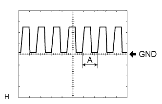
Waveform 1
Item Description Terminal CLTS (H7-25) - GND (5E-12) Gauge 5 V/DIV, 5 ms/DIV Condition Ignition switch ON, Headlight dimmer switch AUTO Tech Tips
If the ambient light becomes brighter, width A becomes narrower.
-
-