LIGHTING SYSTEM TERMINALS OF ECU

-
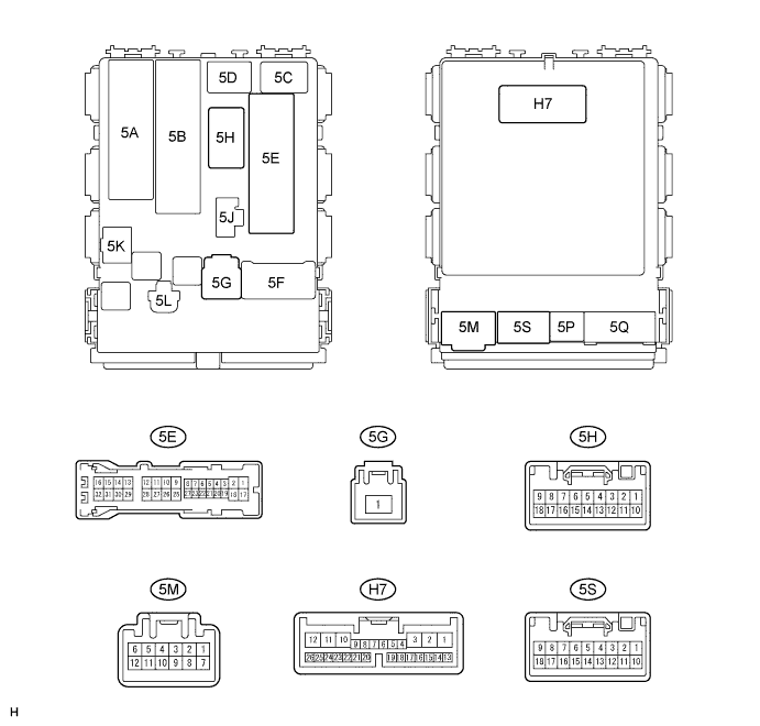
Instrument panel J/B assembly (w/ Automatic light control system)
-
Disconnect the 5E, 5G, and 5M instrument J/B connectors.
-
Measure the voltage and resistance between the wire harness side connectors and body ground.
If the result is not as specified, there may be a malfunction on the wire harness side.
-
Reconnect the 5E, 5G, and 5M instrument J/B connectors.
-
Measure the resistance and voltage according to the value(s) in the table below.
If the result is not as specified, the body ECU may have a malfunction.
*1: LHD
*2: RHD
-
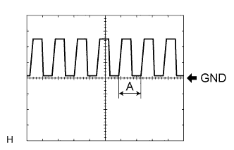
Waveform 1
Item Description Terminal CLTS - CLTE Gauge 5 V/DIV, 5 ms/DIV Condition Ignition switch ON, Headlight dimmer SW in AUTO Tech Tips
If the ambient light becomes brighter, width A becomes narrower.
-
-