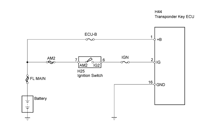
ENGINE IMMOBILISER SYSTEM Power Source Circuit
DESCRIPTION
This circuit provides power to operate the transponder key ECU.
WIRING DIAGRAM
INSPECTION PROCEDURE
PROCEDURE
-
INSPECT FUSE (ECU-B, IGN)
-
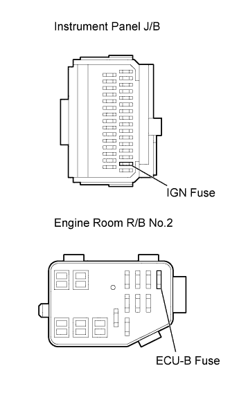
Remove the ECU-B fuse from the engine room R/B No, 2.
-
Remove the IGN fuse from the instrument panel J/B.
-
Check the ECU-B and IGN fuses resistance.
Standard resistance Below 1 Ω -
Reinstall the fuses.
NG 
REPLACE FUSE
OK 
-
-
INSPECT IGNITION SWITCH ASSEMBLY
-
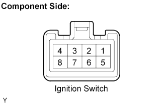
Remove the ignition switch.
-
Check the resistance.
Standard resistance Tester Connection Switch Condition Specified Condition 6 (IG2) - 7 (AM2) LOCK 10 kΩor higher ON, START Below 1 Ω -
Reinstall the ignition switch.
NG
REPLACE IGNITION SWITCH ASSEMBLY
OK
-
-
CHECK HARNESS AND CONNECTOR (TRANSPONDER KEY ECU - BATTERY AND BODY GROUND)
-
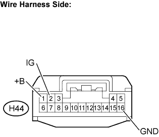
Disconnect the H44 transponder key ECU connector.
-
Check the resistance.
Standard resistance Tester Connection Condition Specified Condition H44-16 (GND) - Body ground Always Below 1 Ω Standard voltage Tester Connection Condition Specified Condition H44-1 (+B) - Body ground Always 11 to 14 V H44-2 (IG) - Body ground Ignition switch OFF Below 1 V Ignition switch ON 11 to 14 V -
Reconnect the transponder key ECU connector.
NG
REPAIR OR REPLACE HARNESS OR CONNECTOR
OK 
PROCEED TO NEXT CIRCUIT INSPECTION SHOWN IN PROBLEM SYMPTOMS TABLE Click here
-