ENGINE IMMOBILISER SYSTEM, Diagnostic DTC:B279A

| DTC Code | DTC Name |
|---|---|
| B279A | Theft Deterrent System Communication Line High Fixation |
DESCRIPTION
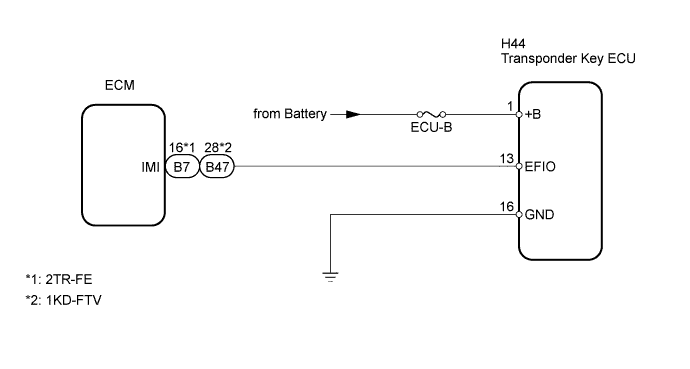
If the communication line (EFIO - IMI) to the transponder key ECU is stuck on HI output, the ECM stores this DTC.
| DTC No. | DTC Detection Condition | Trouble Area |
|---|---|---|
| B279A | The communication line (EFIO - IMI) between the ECM and the transponder key ECU is stuck on HI output. |
|
WIRING DIAGRAM
INSPECTION PROCEDURE
Note
Inspect the fuses for circuits related to this system before performing the following inspection procedure.
PROCEDURE
-
CLEAR DTC
-
Clear the DTCs.
NEXT 
-
-
CHECK FOR DTC
-
Check for DTCs.
Result Result Proceed to DTC B279A is output A DTC B279A and other DTCs are output B
B 
GO TO DIAGNOSTIC TROUBLE CODE CHART
A
-
-
CHECK HARNESS AND CONNECTOR (TRANSPONDER KEY ECU - ECM)
-
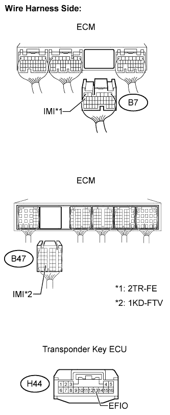
Disconnect the H44 transponder key ECU connector.
-
Disconnect the B7*1 or B47*2 ECM connector.
-
*1: 2TR-FE
-
*2: 1KD-FTV
-
-
Measure the resistance of the wire harness side connectors.
Standard resistance (Check for open) 2TR-FE Tester Connection Specified Condition H44-13 (EFIO) - B7-16 (IMI) Below 1 Ω 1KD-FTV Tester Connection Specified Condition H44-13 (EFIO) - B47-28 (IMI) Below 1 Ω Standard resistance (Check for short) 2TR-FE Tester Connection Specified Condition H44-13 (EFIO) or B7-16 (IMI) - Body ground 10 kΩ or higher 1KD-FTV Tester Connection Specified Condition H44-13 (EFIO) or B47-28 (IMI) - Body ground 10 kΩ or higher -
Reconnect the ECM connector.
-
Reconnect the transponder key ECU connector.
NG
REPAIR OR REPLACE HARNESS OR CONNECTOR
OK
-
-
CHECK ECM (INPUT)
-
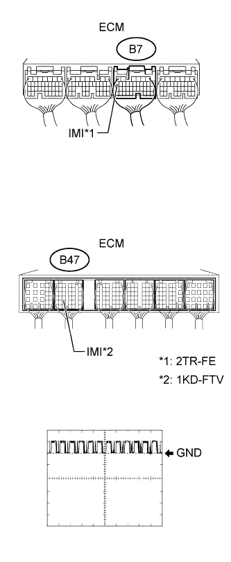
Using an oscilloscope, check the waveform.
2TR-FE Tester Connection Tool Setting Condition Specified Condition B7-16 (IMI) - Body ground 10 V/DIV., 100 ms./DIV. Ignition switch ON See waveform 1KD-FTV Tester Connection Tool Setting Condition Specified Condition B47-28 (IMI) - Body ground 10 V/DIV., 100 ms./DIV. Ignition switch ON See waveform OK Waveform is output normally (refer to illustration).
NG 
CHECK HARNESS AND CONNECTOR (TRANSPONDER KEY ECU - BATTERY AND BODY GROUND) Click here
OK 
REPLACE ECM
-
-
CHECK HARNESS AND CONNECTOR (TRANSPONDER KEY ECU - BATTERY AND BODY GROUND)
-
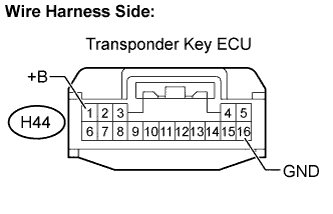
Disconnect the H44 transponder key ECU connector.
-
Measure the voltage of the wire harness side connectors.
Standard voltage Tester Connection Specified Condition H44-1 (+B) - Body ground 11 to 14 V -
Measure the resistance of the wire harness side connectors.
Standard resistance Tester Connection Specified Condition H44-16 (GND) - Body ground Below 1 Ω
NG
REPAIR OR REPLACE HARNESS OR CONNECTOR
OK
-
-
REPLACE TRANSPONDER KEY ECU
-
Temporarily replace the transponder key ECU with a new one.
NEXT
-
-
REGISTER ECU COMMUNICATION ID
-
Register the ECU communication ID.
NEXT
-
-
CLEAR DTC
-
Clear the DTCs.
NEXT
-
-
CHECK FOR DTC
-
Check for DTCs.
OK DTC B279A is not output.
NG
REPLACE ECM
OK
END (TRANSPONDER KEY ECU IS DEFECTIVE)
-