ENGINE IMMOBILISER SYSTEM, Diagnostic DTC:B2784

| DTC Code | DTC Name |
|---|---|
| B2784 | Antenna Coil Open / Short |
DESCRIPTION
The transponder key coil receives key code signals from the key's transponder chip. The coil is built into the transponder key amplifier, which amplifies the key code signals and outputs the signals to the transponder key ECU.
| DTC No. | DTC Detection Condition | Trouble Area |
|---|---|---|
| B2784 | Antenna coil open / short |
|
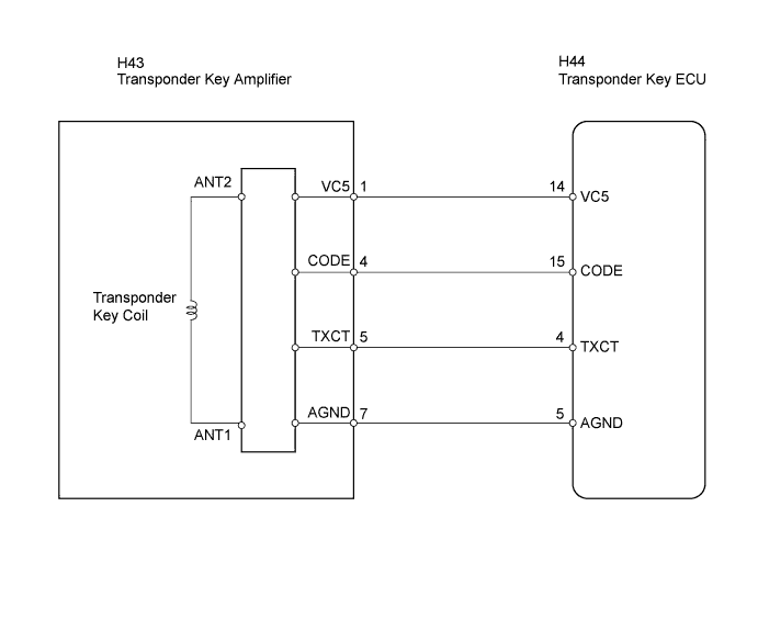
WIRING DIAGRAM
INSPECTION PROCEDURE
PROCEDURE
-
READ VALUE USING INTELLIGENT TESTER (TRANSPONDER KEY COIL)
-
Check the Data List for proper functioning of the transponder key coil.
Transponder key ECU assembly: Item Measurement Item / Display (Range) Normal Condition Diagnostic Note Antenna Coil Status Transponder key coil condition / NORMAL or FAIL NORMAL: Transponder key coil is normal
FAIL: Transponder key coil is malfunctioning
- OK NORMAL (transponder key coil is normal) appears on screen.
OK 
REPLACE TRANSPONDER KEY ECU
NG 
-
-
CHECK HARNESS AND CONNECTOR (TRANSPONDER KEY ECU - TRANSPONDER KEY AMPLIFIER)
-
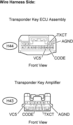
Disconnect the H44 transponder key ECU connector.
-
Disconnect the H43 transponder key amplifier connector.
-
Check the resistance.
Standard resistance (Check for open) Tester Connection Specified Condition H44-14 (VC5) - H43-1 (VC5) Below 1 Ω H44-15 (CODE) - H43-4 (CODE) H44-4 (TXCT) - H43-5 (TXCT) H44-5 (AGND) - H43-7 (AGND) Standard resistance (Check for short) Tester Connection Specified Condition H44-14 (VC5) or H43-1 (VC5) - Body ground 10 kΩ or higher H44-15 (CODE) or H43-4 (CODE) - Body ground H44-4 (TXCT) or H43-5 (TXCT) - Body ground -
Reconnect the transponder key amplifier connector.
-
Reconnect the transponder key ECU connector.
NG
REPAIR OR REPLACE HARNESS OR CONNECTOR
OK 
REPLACE TRANSPONDER KEY AMPLIFIER
-