ENGINE IMMOBILISER SYSTEM, Diagnostic DTC:B2780

| DTC Code | DTC Name |
|---|---|
| B2780 | Push Switch / Key Unlock Warning Switch Malfunction |
DESCRIPTION
This DTC will be output if the transponder key ECU does not detect that the unlock warning switch is ON even when the key is inserted into the ignition key cylinder. Under normal conditions, the unlock warning switch is ON when the key is inserted into the ignition key cylinder.
| DTC No. | DTC Detection Condition | Trouble Area |
|---|---|---|
| B2780 | Unlock warning switch ON is not detected when key is inserted into ignition key cylinder |
|
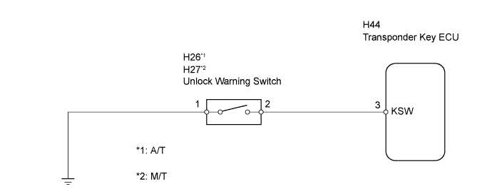
WIRING DIAGRAM
INSPECTION PROCEDURE
PROCEDURE
-
READ VALUE USING INTELLIGENT TESTER (UNLOCK WARNING SWITCH ASSEMBLY)
-
Check the Data List for proper functioning of the unlock warning switch.
Transponder key ECU: Item Measurement Item/Display (Range) Normal Condition Diagnostic Note Key SW Unlock warning switch signal / ON or OFF OFF: No key is in ignition key cylinder
ON: Key is in ignition key cylinder
- OK ON (key is in ignition key cylinder) appears on screen.
OK 
REPLACE TRANSPONDER KEY ECU
NG 
-
-
INSPECT UNLOCK WARNING SWITCH ASSEMBLY
-
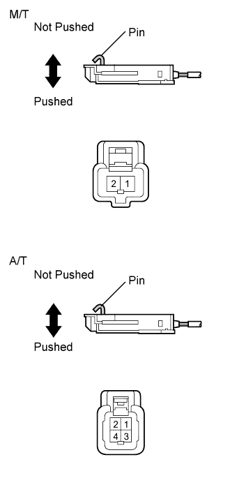
Remove the unlock warning switch.
-
Measure the resistance of the switch.
Standard resistance Tester Connection Switch Condition Specified Condition 1 - 2 Pushed Below 1 Ω Not pushed 10 kΩ or higher -
Reinstall the unlock warning switch.
NG
REPLACE UNLOCK WARNING SWITCH ASSEMBLY
OK
-
-
CHECK HARNESS AND CONNECTOR (UNLOCK WARNING SWITCH - TRANSPONDER KEY ECU AND BODY GROUND)
-
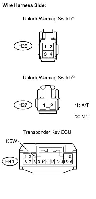
Disconnect the H26*1, H27*2unlock warning switch connector.
-
Disconnect the H44 transponder key ECU connector.
-
Measure the resistance of the wire harness side connectors.
Standard resistance Tester Connection Specified Condition H44-3 (KSW) - H26-2*1
H44-3 (KSW) - H27-2*2
Below 1 Ω H26-1*1- Body ground
H27-1*2- Body ground
*1: A/T
*2: M/T
-
Reconnect the unlock warning switch connector.
-
Reconnect the transponder key ECU connector.
NG
REPAIR OR REPLACE HARNESS OR CONNECTOR
OK 
REPLACE TRANSPONDER KEY ECU
-