AIRBAG SYSTEM, Diagnostic DTC:B1662/45

| DTC Code | DTC Name |
|---|---|
| B1662/45 | Indicator Light Circuit Malfunction |
DESCRIPTION
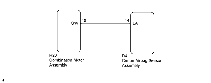
The indicator light circuit consists of the center airbag sensor assembly and combination meter assembly. If the center airbag sensor assembly detects a malfunction in the airbag system, the SRS warning light will come on to inform the driver.
DTC B1662/45 is stored when a malfunction is detected in the indicator light circuit.
| DTC No. | Detection Condition | Trouble Area |
|---|---|---|
| B1662/45 |
|
|
WIRING DIAGRAM
INSPECTION PROCEDURE
PROCEDURE
-
CHECK CONNECTORS
-
Turn the ignition switch off.
-
Disconnect the cable from the negative (-) battery terminal.
CAUTION:
Wait at least 90 seconds after disconnecting the cable from the negative (-) battery terminal to disable the SRS system.
-
Check that the connectors are properly connected to the center airbag sensor assembly and combination meter assembly.
OK The connectors are properly connected. Tech Tips
If the connectors are not properly connected, reconnect the connectors and proceed to the next inspection.
-
Disconnect the connectors from the center airbag sensor assembly and combination meter assembly.
-
Check that the terminals of the connectors are not damaged.
OK The terminals are not deformed or damaged.
NG 
REPAIR OR REPLACE INSTRUMENT PANEL WIRE
OK 
-
-
CHECK INSTRUMENT PANEL WIRE (SHORT TO GROUND)
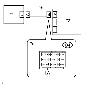
Text in Illustration *1 Combination Meter Assembly *2 Center Airbag Sensor Assembly *a Connector B *b Instrument Panel Wire
-
Measure the resistance according to the value(s) in the table below.
Standard Resistance Tester Connection Condition Specified Condition B4-14 (LA) - Body ground Always 1 MΩ or higher
NG
REPAIR OR REPLACE INSTRUMENT PANEL WIRE
OK
-
-
CHECK INSTRUMENT PANEL WIRE (OPEN)
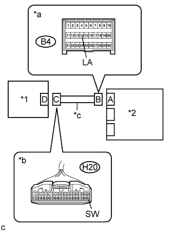
Text in Illustration *1 Combination Meter Assembly *2 Center Airbag Sensor Assembly *a Connector B *b Connector C *c Instrument Panel Wire
-
Measure the resistance according to the value(s) in the table below.
Standard Resistance Tester Connection Condition Specified Condition B4-14 (LA) - H20-40 (SW) Always Below 1 Ω
NG
REPAIR OR REPLACE INSTRUMENT PANEL WIRE
OK
-
-
CHECK INSTRUMENT PANEL WIRE (SHORT TO B+)
Text in Illustration *1 Combination Meter Assembly *2 Center Airbag Sensor Assembly *a Connector B *b Instrument Panel Wire
-
Connect the cable to the negative (-) battery terminal.
-
Measure the voltage according to the value(s) in the table below.
Standard Voltage Tester Connection Condition Specified Condition B4-14 (LA) - Body ground Ignition switch ON Below 1 V
NG
REPAIR OR REPLACE INSTRUMENT PANEL WIRE
OK
-
-
CHECK CENTER AIRBAG SENSOR ASSEMBLY
-
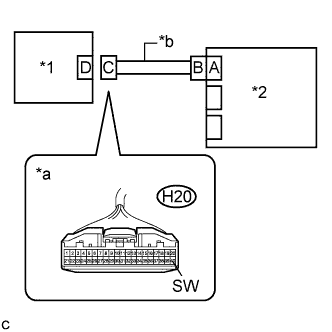
Text in Illustration *1 Combination Meter Assembly *2 Center Airbag Sensor Assembly *a Connector C *b Instrument Panel Wire Turn the ignition switch off.
-
Disconnect the cable from the negative (-) battery terminal.
CAUTION:
Wait at least 90 seconds after disconnecting the cable from the negative (-) battery terminal to disable the SRS system.
-
Connect the connector to the center airbag sensor assembly.
-
Connect the cable to the negative (-) battery terminal.
-
Turn the ignition switch to ON, and wait for at least 60 seconds.
-
Measure the voltage according to the value(s) in the table below.
Standard Voltage Tester Connection Condition Specified Condition H20-40 (SW) - Body ground For 6 seconds after ignition switch turned ON. Below 1 V After 6 seconds have passed since ignition switch turned ON. 11 to 14 V
NG
REPLACE CENTER AIRBAG SENSOR ASSEMBLY
OK 
REPLACE COMBINATION METER ASSEMBLY
-