AIR CONDITIONING CONTROL ASSEMBLY INSPECTION

-
INSPECT HEATER CONTROL KNOB (w/ Air Conditioning System)
-
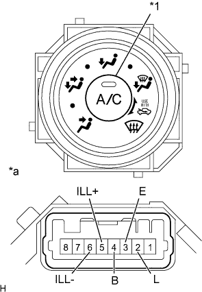
Text in Illustration *1 A/C Switch *a Component without harness connected
(Heater Control Knob)
Measure the resistance according to the value(s) in the table below.
Standard Resistance (for 1KD-FTV, 2KD-FTV, 1TR-FE, 2TR-FE) Tester Connection Switch Condition Specified Condition 4 (B) - 2 (L) A/C switch OFF 10 kΩ or higher A/C switch ON Below 1 Ω Standard Resistance (for 5L-E) Tester Connection Switch Condition Specified Condition 3 (E) - 4 (B) A/C switch OFF 10 kΩ or higher A/C switch ON Below 1 Ω If the result is not as specified, replace the heater control knob.
-
Check the A/C indicator operation.
-
Connect the positive (+) lead from the battery to terminal 2 (L) and the negative (-) lead to terminal 3 (E).
-
Push the air conditioning switch, and check that the indicator light comes on.
OK The indicator light comes on. If the result is not as specified, replace the heater control knob.
-
-
Check the illumination operation.
-
Connect the positive (+) lead from the battery to terminal 5 (ILL+) and the negative (-) lead to terminal 6 (ILL-), and check that the illumination light comes on.
OK The illumination light comes on. If the result is not as specified, replace the bulb.
-
-
-
INSPECT HEATER CONTROL KNOB (w/o Air Conditioning System)
-
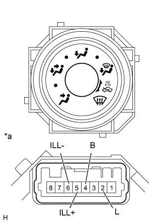
Text in Illustration *a Component without harness connected
(Heater Control Knob)
Measure the resistance according to the value(s) in the table below.
Standard Resistance Tester Connection Switch Condition Specified Condition 2 (L) - 4 (B) Always Below 1 Ω If the result is not as specified, replace the heater control knob.
-
Check the illumination operation.
-
Connect the positive (+) lead from the battery to terminal 5 (ILL+) and the negative (-) lead to terminal 6 (ILL-), and check that the illumination light comes on.
OK The illumination light comes on. If the result is not as specified, replace the bulb.
-
-
-
INSPECT NO. 2 HEATER CONTROL KNOB
-
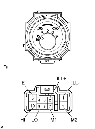
Text in Illustration *a Component without harness connected
(No. 2 Heater Control Knob)
Measure the resistance according to the value(s) in the table below.
Standard Resistance Tester Connection Switch Condition Specified Condition 9 (LO), 7 (M1), 6 (M2), 10 (HI) - 5 (E) Blower switch: 0 10 kΩ or higher 9 (LO) - 5 (E) Blower switch: 1 Below 1 Ω 9 (LO), 7 (M1) - 5 (E) Blower switch: 1 - 2 Below 1 Ω 9 (LO), 7 (M1) - 5 (E) Blower switch: 2 Below 1 Ω 9 (LO), 7 (M1), 6 (M2) - 5 (E) Blower switch: 2 - 3 Below 1 Ω 9 (LO), 6 (M2) - 5 (E) Blower switch: 3 Below 1 Ω 9 (LO), 6 (M2), 10 (HI) - 5 (E) Blower switch: 3 - 4 Below 1 Ω 9 (LO) 10 (HI) - 5 (E) Blower switch: 4 Below 1 Ω If the result is not as specified, replace the No. 2 heater control knob.
-
Check the illumination operation.
-
Connect the positive (+) lead from the battery to terminal 2 (ILL+) and the negative (-) lead to terminal 1 (ILL-), and check that the illumination light comes on.
OK The illumination light comes on. If the result is not as specified, replace the bulb.
-
-
-
INSPECT NO. 3 HEATER CONTROL KNOB (w/ Heater)
-
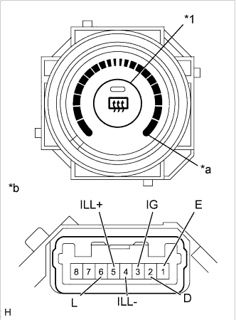
Text in Illustration *1 Rr. DEF Switch *a Max Hot Position *b Component without harness connected
(No. 3 Heater Control Knob)
Measure the resistance according to the value(s) in the table below.
Standard Resistance Tester Connection Switch Condition Specified Condition 3 (IG) - 1 (E) Rr. DEF switch OFF 10 kΩ or higher 3 (IG) - 1 (E) Rr. DEF switch ON Below 1 Ω 3 (IG) - 2 (D) Rr. DEF switch OFF 10 kΩ or higher 3 (IG) - 2 (D) Rr. DEF switch ON Below 1 Ω 3 (IG) - 6 (L) Except MAX HOT 10 kΩ or higher 3 (IG) - 6 (L) MAX HOT Below 1 Ω If the result is not as specified, replace the No. 3 heater control knob.
-
Check the illumination operation.
-
Connect the positive (+) lead from the battery to terminal 5 (ILL+) and the negative (-) lead to terminal 4 (ILL-), and check that the illumination light comes on.
OK The illumination light comes on. If the result is not as specified, replace the bulb.
-
-
-
INSPECT NO. 3 HEATER CONTROL KNOB (w/o Heater)
-
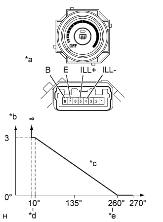
Text in Illustration *a Component without harness connected
(No. 3 Heater Control Knob)
*b Resistance (kΩ) *c Rotation Angle *d MAX HOT *e MAX COOL Turn the No. 3 heater control knob and measure the resistance between terminals 7 (E) and 8 (B).
OK The resistance changes as shown in the illustration. If the result is not as specified, replace the No. 3 heater control knob.
-
Check the illumination operation.
-
Connect the positive (+) lead from the battery to terminal 5 (ILL+) and the negative (-) lead to terminal 4 (ILL-), and check that the illumination light comes on.
OK The illumination light comes on. If the result is not as specified, replace the bulb.
-
-