AIR CONDITIONING CONTROL ASSEMBLY REMOVAL

-
REMOVE INSTRUMENT PANEL FINISH PANEL LOWER
-
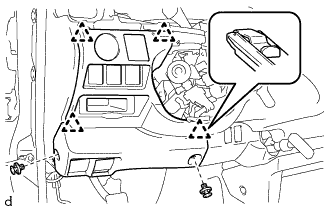
Using a clip remover, remove the 2 clips.
-
Detach the 4 clips and remove the instrument panel finish lower.
-
Disconnect each connector.
-
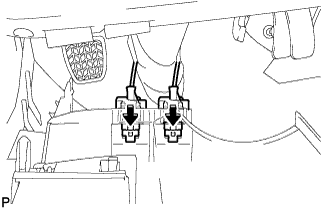
Push the positions indicated by the arrows in the illustration to disconnect the fuel lid lock control cable and bonnet (hood) control cable assembly from the instrument panel finish lower.
-
-
REMOVE INSTRUMENT PANEL NO. 1 UNDER COVER SUB-ASSEMBLY
-
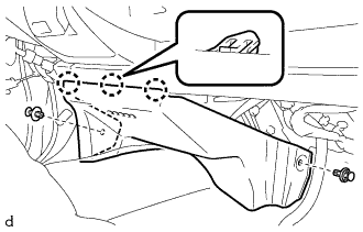
Using a clip remover, remove the 2 clips
-
Detach the 3 claws and remove the instrument panel under cover sub-assembly No. 1.
-
-
REMOVE PARKING BRAKE HOLE COVER
-
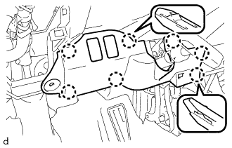
Detach the 6 claws and remove the parking brake hole cover.
-
Disconnect each connector.
-
-
REMOVE SHIFT LEVER KNOB
-
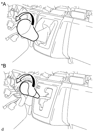
Text in Illustration *A for Manual Transmission *B for Automatic Transmission Turn the shift lever knob in the direction indicated by the arrow and remove it.
-
-
REMOVE SHIFTING HOLE COVER ASSEMBLY
-
Detach the 6 claws and remove the parking brake hole cover.
-
Disconnect each connector.
-
-
REMOVE INSTRUMENT PANEL FINISH PANEL LOWER CENTER
-
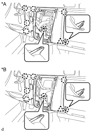
Text in Illustration *A for Manual Transmission *B for Automatic Transmission Detach the 8 claws and remove the instrument panel finish panel lower center.
-
-
REMOVE INSTRUMENT CLUSTER FINISH PANEL SUB-ASSEMBLY LOWER CENTER (AIR CONDITIONING CONTROL ASSEMBLY)
-
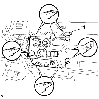
Text in Illustration *1 Protective Tape Put protective tape around the instrument cluster finish panel sub-assembly lower center.
-
Detach the 8 claws and separate the instrument cluster finish panel sub-assembly lower center (air conditioning control assembly).
-
Disconnect the connector.
-
Disconnect the cable from the clamp.
-
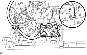
Detach the 2 claws and disconnect the air inlet damper control cable sub-assembly from the No. 2 heater control knob.
-
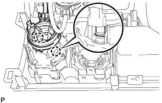
Detach the 2 claws and disconnect the heater control cable sub-assembly from the heater control knob.
-
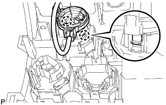
w/ No. 3 Heater Control Knob:
Detach the 2 claws and disconnect the air mix damper control cable sub-assembly from the No. 3 heater control knob and remove the instrument cluster finish panel sub-assembly lower center (air conditioning control assembly).
-