AIR MIX DAMPER CONTROL SWITCH INSPECTION

-
INSPECT AIR MIX DAMPER CONTROL SWITCH
-
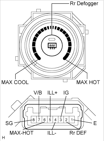
Remove the air mix damper control switch and disconnect the connector.
-
Measure the resistance according to the value(s) in the table below.
Standard resistance Tester connection Condition Specified condition 3 (IG) - 1 (E) Rr. DEF switch OFF 10 kΩ or higher 3 (IG) - 1 (E) Rr. DEF switch ON Below 1 Ω 3 (IG) - 2 (Rr DEF) Rr. DEF switch OFF 10 kΩ or higher 3 (IG) - 2 (Rr DEF) Rr. DEF switch ON Below 1 Ω 3 (IG) - 6 (MAX HOT) Except MAX HOT 10 kΩ or higher 3 (IG) - 6 (MAX HOT) MAX HOT Below 1 Ω 4 (ILL-) - 5 (ILL+) Always Below 1 Ω 7 (V/B) - 8 (SG) MAX HOT 10 kΩ or higher 7 (V/B) - 8 (SG) Except MAX HOT Below 1 Ω If the resistance value is not as specified, replace the air mix damper control switch.
-
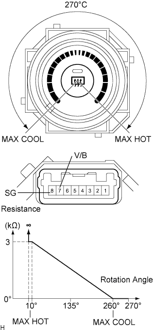
Turn the heater control knob and measure the resistance between terminals 7 (V/B) and 8 (SG).
OK The resistance changes as shown in the illustration. If the resistance value is not as specified, replace the air mix damper control switch.
-
Connect the positive battery terminal to terminal 5 (ILL+), and the negative battery terminal to terminal 4 (ILL-).
OK The illumination light comes on. If the resistance value is not as specified, replace the air mix damper control switch.
-
Connect the positive battery terminal to terminal 3 (IG), and the negative battery terminal to terminal 1 (E).
OK The indicator light comes on when the Rr DEF switch is turned on. If the resistance value is not as specified, replace the air mix damper control switch.
-