REAR COOLING UNIT (for Integrated Blower Motor Fan Type) INSTALLATION

-
INSTALL REAR COOLING UNIT
-
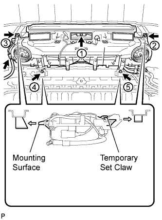
Temporarily set the mounting surface at the front of the cooling unit into the roof reinforcement bracket.
-
Temporarily set the temporary set claws at the back of the cooling unit into the roof reinforcement bracket.
-
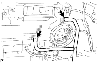
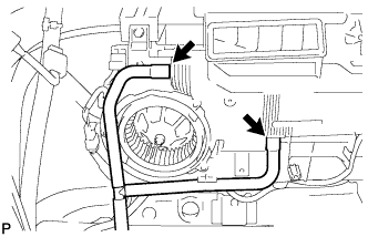
Install the rear cooling unit with the 5 bolts.
Note
Tighten the bolts in the order shown in the illustration to install the rear cooling unit.
-
Connect the connector.
-
-
INSTALL AIR CONDITIONING TUBE AND ACCESSORY ASSEMBLY (except Super Long Wheelbase)
-
Remove the attached vinyl tape from the hose.
-
Apply sufficient compressor oil (ND-OIL 8) to a new O-ring and the fitting surface of the rear cooling unit.
Compressor oil ND-OIL 8 or equivalent -
Install the O-ring onto the air conditioning tube and accessory assembly.
-
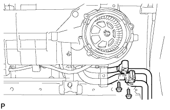
Install the air conditioning tube and accessory assembly onto the rear cooling unit with the 2 bolts.
- Torque:
- 5.4 N*m { 55 kgf*cm, 48 in.*lbf }
-
-
INSTALL AIR CONDITIONING TUBE AND ACCESSORY ASSEMBLY (for Super Long Wheelbase)
-
Remove the attached vinyl tape from the hose.
-
Apply sufficient compressor oil (ND-OIL 8) to a new O-ring and the fitting surface of the rear cooling unit.
Compressor oil ND-OIL 8 or equivalent -
Install the O-ring onto the air conditioning tube and accessory assembly.
-
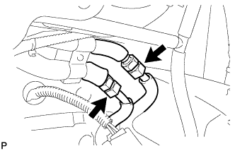
Install the air conditioning tube and accessory assembly onto the rear cooling unit with the 2 union nuts.
Note
Do not apply excessive force to the pipes.
- Torque:
- 23 N*m { 235 kgf*cm, 17 ft.*lbf }
-
-
INSTALL COOLER REFRIGERANT HOSE NO. 1 INSULATOR
-
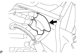
Install the new cooler refrigerant hose No. 1 insulator.
-
-
CONNECT COOLER UNIT NO. 3 DRAIN HOSE
-
Connect the cooler unit No. 3 drain hose.
-
-
CONNECT COOLER UNIT NO. 2 DRAIN HOSE
-
Connect the cooler unit No. 2 drain hose.
-
-
INSTALL ROOF NO. 1 HEADLINING (for Full-trim)
Tech Tips
Refer to the instructions for installation of the instrument panel assembly. Click here
-
INSTALL ROOF NO. 1 HEADLINING (for Semi-trim)
Tech Tips
Refer to the instructions for installation of the instrument panel assembly. Click here
-
CHARGE REFRIGERANT
-
Perform vacuum purging using a vacuum pump.
-
Charge with refrigerant HFC-134a (R134a).
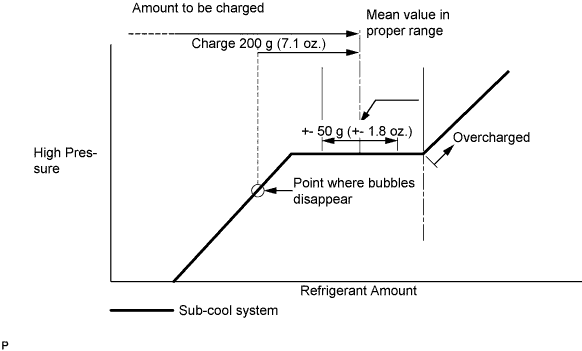
Standard Single A/C 520 to 580g (18.3 to 20.5 oz.) Dual A/C 670 to 730g (23.0 to 25.7 oz.) - SST
- 07110-58060 ( 07117-58090, 07117-78050, 07117-58070, 07117-58060, 07117-58080, 07117-88060, 07117-88070, 07117-88080 )
Note
-
Do not operate the cooler compressor before charging refrigerant as the cooler compressor does not work properly without any refrigerant, which causes the compressor to overheat.
-
Approximately 100 g (3.5 oz.) of refrigerant may need to be charged after bubbles disappear. The refrigerant amount should be checked by quantity, and not with the sight glass.
Tech Tips
Prepare a service can to recharge refrigerant if using the refrigerant gas collected with the freon collection/recycling device because the collective rate of the device is approximately 90%.
-
-
WARM UP ENGINE
-
Warm up the engine at less than 1,850 rpm for 2 minutes or more after charging refrigerant.
Note
Be sure to warm up the compressor when turning the A/C switch on after removing and installing the cooler refrigerant lines (including the compressor), to prevent damage to the compressor.
-
-
CHECK FOR LEAKAGE OF REFRIGERANT
-
After recharging refrigerant gas, check for leakage of refrigerant gas using a halogen leak detector.
-
Carry out the test under the following conditions:
-
Stop the engine.
-
Secure good ventilation (the gas leak detector may react to volatile gases which are not refrigerant, such as evaporated gasoline and exhaust gas).
-
Repeat the test 2 or 3 times.
-
Make sure that there is some refrigerant remaining in the refrigeration system.
When the compressor is off: approx. 392 to 588 kPa (4 to 6 kgf/cm2, 57 to 85 psi)
-
-
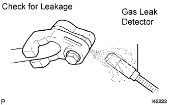
Using a gas leak detector, check for leakage of the refrigerant line.
-
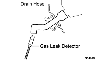
Bring the gas leak detector close to the drain hose with the detector's power off.
Tech Tips
-
After the blower motor has stopped, let the cooling unit stand for more than 15 minutes.
-
Bring the gas leak detector sensor under the drain hose.
-
When bringing the gas leak detector close to the drain hose, make sure that the gas leak detector does not react to volatile gases.
If such reaction is unavoidable, the vehicle must be lifted up.
-
-
If a gas leak is not detected on the drain hose, remove the blower motor control from the cooling unit. Insert the gas leak detector sensor into the unit and perform the test.
-
Disconnect the pressure switch connector and leave it for approximately 20 minutes. Bring the gas leak detector close to the pressure switch and perform the test.
-