AIR CONDITIONING UNIT INSTALLATION

-
INSTALL AIR CONDITIONING RADIATOR ASSEMBLY
-
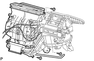
Install the air conditioning radiator assembly with the 3 screws.
-
w/ PTC
-
Install the wire harness with the screw.
-
-
-
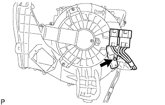
INSTALL AIR DUCT NO.2
-
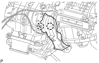
Engage the 2 claws to install the air duct No.2.
-
-
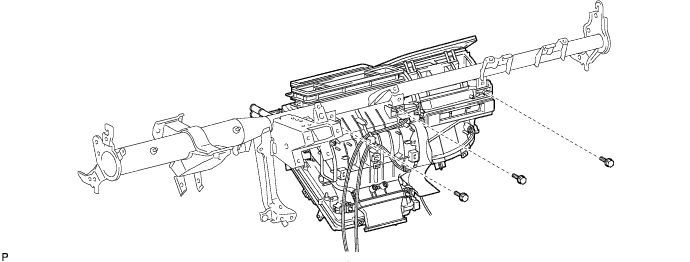
INSTALL AIR CONDITIONER UNIT ASSEMBLY
-
Install the air conditioner unit assembly with the 3 bolts.
-
-
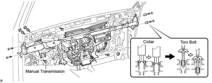
INSTALL INSTRUMENT PANEL REINFORCEMENT ASSEMBLY
-
Driver seat:
-
Using a "Torx" socket wrench (T40), install the instrument panel reinforcement assembly with the 2 Torx bolts.
-
-
Passenger seat:
-
Using a hexagon wrench 12 mm, install the instrument panel reinforcement assembly with the 2 bolts.
- Torque:
- 6.0 N*m { 61 kgf*cm, 53 in.*lbf }
-
Using a "Torx" socket wrench (T40), install the instrument panel reinforcement assembly with the 2 "Torx" bolts.
- Torque:
- 20 N*m { 204 kgf*cm, 15 ft.*lbf }
-
-
Install the 2 bolts and nut. (AUTOMATIC TRANSMISSION)
-
Install the 3 bolts and nut. (MANUAL TRANSMISSION)
-
Install the 2 bolts and cap.
-
-
INSTALL INSTRUMENT PANEL TO FLOOR BRACE SUB-ASSEMBLY
-
CONNECT PARKING BRAKE CONTROL HANDLE SUB-ASSEMBLY
-
INSTALL AIR DUCT NO.1
-
INSTALL STEERING COLUMN ASSEMBLY
-
Install the steering column assembly Click here.
-
-
INSTALL STEERING INTERMEDIATE SHAFT
-
Install the steering intermediate shaft Click here.
-
-
INSTALL INSTRUMENT PANEL ASSEMBLY
Tech Tips
Refer to the instructions for installation of the instrument panel assembly. Click here
-
INSTALL HEATER WATER HOSE INLET A
-
INSTALL HEATER WATER HOSE OUTLET
-
INSTALL COOLER REFRIGERANT LIQUID PIPE B
-
Remove the attached vinyl tape from the pipe.
-
Sufficiently apply compressor oil to a new O-ring and the fitting surface of the cooler refrigerant liquid pipe B.
Compressor oil ND-OIL 8 or equivalent -
Install the O-ring on the cooler refrigerant liquid pipe B.
-
Install the cooler refrigerant liquid pipe B.
-
-
INSTALL COOLER REFRIGERANT SUCTION PIPE A
-
Remove the attached vinyl tape from the hose.
-
Sufficiently apply compressor oil to a new O-ring and the fitting surface of the cooler refrigerant suction pipe A.
Compressor oil ND-OIL 8 or equivalent -
Install the O-ring on the cooler refrigerant suction pipe A.
-
Move the hook connector in the direction indicated by the arrow in the illustration.
-
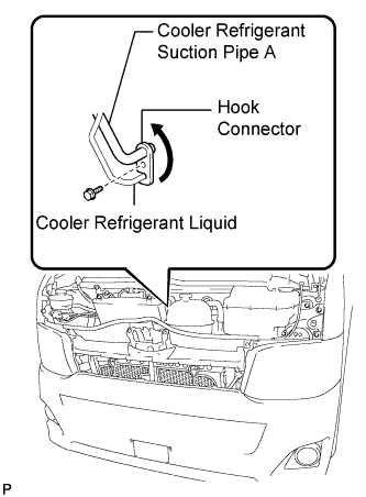
Insert the pipe joints into the fitting holes securely and tighten the bolt.
- Torque:
- 9.8 N*m { 100 kgf*cm, 87 in.*lbf }
-
-
INSTALL INTERCOOLER ASSEMBLY (w/ Intercooler)
-
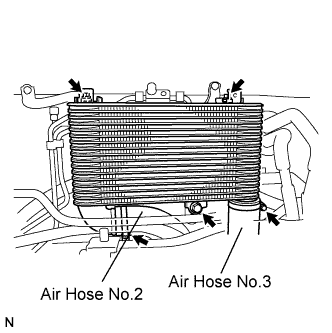
Temporarily install the intercooler assembly with the 3 bolts.
-
Connect the air hose No.2, and tighten the clamp.
-
Connect the air hose No.3, and tighten the clamp.
-
Tighten the intercooler assembly.
- Torque:
- 18 N*m { 180 kgf*cm, 13 ft.*lbf }
- 6.0 N*m { 61 kgf*cm, 53 in.*lbf }
-
-
INSTALL RADIATOR SUPPORT SUB-ASSEMBLY (w/ Intercooler)
-
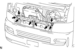
Install the radiator upper support with the 6 bolts and 2 screws.
- Torque:
- 5.5 N*m { 56 kgf*cm, 49 in.*lbf }
Tech Tips
If the position of the radiator upper support goes out of alignment while installing it, remove the front bumper and adjust the hood lock brace and bumper stay.
-
-
INSTALL HOOD LOCK ASSEMBLY (w/ Intercooler)
-
Connect the hood lock cable assembly to the hood lock assembly.
-
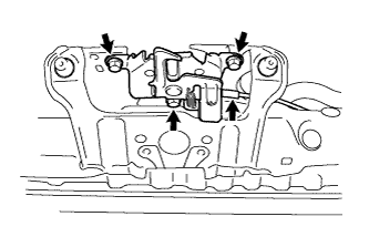
Temporarily tighten the hood lock assembly with the 3 bolts from the radiator upper support.
-
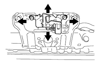
Check the hood position and adjust the hood lock assembly position.
-
Tighten the hood lock assembly with the 3 bolts.
- Torque:
- 12 N*m { 122 kgf*cm, 9 ft.*lbf }
-
-
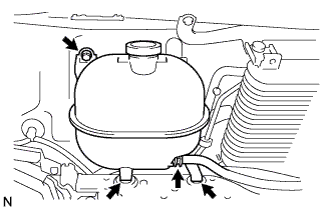
INSTALL RADIATOR RESERVE TANK ASSEMBLY (w/ Intercooler)
-
Connect the water by-pass hose No.2 with the clip.
-
Connect the water by-pass hose No.1 with the clip.
-
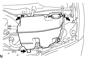
Place the reserve tank in the 2 grommets of the radiator upper support, and install the radiator reserve tank assembly with the bolt.
- Torque:
- 7.0 N*m { 71 kgf*cm, 62 in.*lbf }
-
-
INSTALL WINDSHIELD WASHER JAR ASSEMBLY (w/ Rear Wiper and Intercooler)
-
Connect the 2 connectors and 2 hoses.
-
Install the wind washer jar assembly with the 2 bolts.
- Torque:
- 4.9 N*m { 50 kgf*cm, 43 in.*lbf }
-
-
INSTALL WINDSHIELD WASHER JAR ASSEMBLY (w/o Rear Wiper and w/ Intercooler)
-
Connect the connector and hose.
-
Install the wind washer jar assembly with the 2 bolts.
- Torque:
- 4.9 N*m { 50 kgf*cm, 43 in.*lbf }
-
-
ADD WINDSHIELD WASHER FLUID (w/ Intercooler)
-
INSTALL AIR INLET DUCT (w/ Intercooler)
-
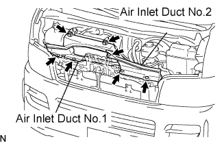
Install the air inlet duct No.1 with the 2 bolts and 2 clips.
- Torque:
- 7.0 N*m { 71 kgf*cm, 62 in.*lbf }
-
Install the air inlet duct No.2 with the 3 clips.
-
-
INSTALL RADIATOR GRILLE (for Standard Body)
-
Attach the 6 claws and 2 clips to install the radiator grille.
-
Install the 4 clips and 2 screws.
-
-
INSTALL RADIATOR GRILLE (for Wide Body)
-
Attach the 6 claws and 2 clips to install the radiator grille.
-
Install the 4 clips and 2 screws.
-
-
INSTALL ENGINE UNDER COVER NO.1 (w/ Intercooler)
-
INSTALL WIPER LINK ASSEMBLY
-

Engage the grommet as shown in the illustration.
-
Install the windshield wiper motor and link assembly with the 2 bolts.
- Torque:
- 5.4 N*m { 55 kgf*cm, 48 in.*lbf }
-
Connect the connector.
-
-
INSTALL COWL TOP VENTILATOR LOUVER SUB-ASSEMBLY
-
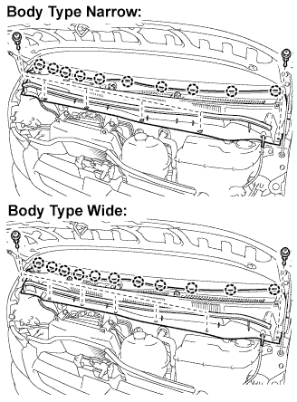
Body type narrow:
-
Install the cowl top ventilator louver sub-assembly with the 10 claws and 6 clips.
-
-
Body type wide:
-
Install the cowl top ventilator louver sub-assembly with the 11 claws and 7clips.
-
-
Connect the washer hose.
-
-
INSTALL COWL VENT COVER LH
-
INSTALL COWL VENT COVER RH
-
INSTALL FRONT WIPER ARM AND BLADE ASSEMBLY LH
-
Operate the wiper, and stop the windshield wiper motor assembly at the automatic stop position.
-
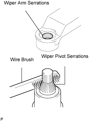
Clean the wiper arm serrations.
-
Clean the wiper pivot serrations with a wire brush (when reinstalling).
-
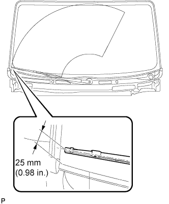
Install the front wiper arm and blade assembly LH with the nut at the position as shown in the illustration.
- Torque:
- 25 N*m { 225 kgf*cm, 18 ft.*lbf }
Tech Tips
Hold the arm hinge by hand to fasten the nut.
-
-
INSTALL FRONT WIPER ARM AND BLADE ASSEMBLY RH
-
Clean the wiper arm serrations.
-
Clean the wiper pivot serrations with a wire brush (when reinstalling).
-
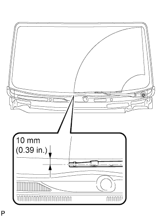
Install the front wiper arm and blade assembly RH with the nut at the position as shown in the illustration.
- Torque:
- 25 N*m { 225 kgf*cm, 18 ft.*lbf }
Tech Tips
Hold the arm hinge by hand to fasten the nut.
-
-
INSTALL WINDSHIELD WIPER ARM COVER
-
Install the 2 windshield wiper arm covers.
-
Operate the front wipers while spraying water or washer fluid on the windshield. Make sure that the wipers function properly and there is no interference with the vehicle body.
-
-
CONNECT CABLE TO NEGATIVE BATTERY TERMINAL
- Torque:
- 5.4 N*m { 55 kgf*cm, 48 in.*lbf }
Note
When disconnecting the cable, some systems need to be initialized after the cable is reconnected Click here.
-
ADD ENGINE COOLANT (2KD-FTV Type:)
-
Firmly tighten the drain plugs.
-
Fill the radiator reservoir with coolant to the top of the inlet.
Standard Capacity Item Specified Condition w/o Heater 13.6 liters (14.4 US qts, 12.0 Imp. qts) w/ Front Heater 14.6 liters (15.4 US qts, 12.8 Imp. qts) w/ Front and Rear Heaters 16.6 liters (17.5 US qts, 14.6 Imp. qts) Note
Do not substitute plain water for engine coolant.
Tech Tips
-
Use of improper coolants may damage the engine cooling system.
-
Use only Toyota Super Long Life Coolant or similar high quality ethylene glycol based non-silicate, non-amine, non-nitrite, and non-borate coolant with long-life hybrid organic acid technology (coolant with long-life hybrid organic acid technology consists of a combination of low phosphates and organic acids).
-
-
Loosen the bleeder plug of the outlet housing.
-
When air is bled and the coolant drains out, firmly tighten the bleeder plug.
- Torque:
- 8.0 N*m { 82 kgf*cm, 71 in.*lbf }
-

Add coolant up to the B line mark in the radiator reservoir and install the reservoir cap.
-
Warm up the engine until the thermostat opens.
-
While the thermostat is open, circulate the coolant for several minutes.
Tech Tips
The thermostat open timing can be confirmed by pressing the inlet radiator hose by hand, and checking when the engine coolant starts to flow inside the hose.
-
-

After the engine cools down, check that the coolant level is between the LOW and FULL level marks.
-
-
ADD ENGINE COOLANT (2TR-FE Type:)
-
Firmly tighten the drain plugs and fill the reservoir tank with coolant to the top of the inlet.
-
Remove the 2-way that is located near the throttle body.
-
When air is bled and the coolant drains out, firmly install the 2-way.
-
Add coolant up to the B line mark in the reservoir tank and install the radiator cap.
Coolant Capacity Condition Capacity w/ front and rear heaters 13.6 liters (14.4 US qts, 12.0 lmp. qts) w/ front heater 11.6 liters (12.3 US qts, 10.2 lmp. qts) w/o heater 10.6 liters (11.2 US qts, 9.3 lmp. qts) -
Warm up the engine.
-
After the engine cools down, check that the coolant level is between the LOW and FULL level marks.
-
-
ADD ENGINE COOLANT (5L-E Type:)
-
Firmly tighten the drain plugs.
-
Fill the radiator reservoir with coolant to the top of the inlet.
Standard Capacity Item Specified Condition w/o Heater 12.7 liters (13.4 US qts, 11.2 Imp. qts) w/ Front Heater 13.7 liters (14.5 US qts, 12.1 Imp. qts) w/ Front and Rear Heaters 15.7 liters (16.6 US qts, 13.8 Imp. qts) Note
Do not substitute plain water for engine coolant.
Tech Tips
-
Use of improper coolants may damage the engine cooling system.
-
Use only Toyota Super Long Life Coolant or similar high quality ethylene glycol based non-silicate, non-amine, non-nitrite, and non-borate coolant with long-life hybrid organic acid technology (coolant with long-life hybrid organic acid technology consists of a combination of low phosphates and organic acids).
-
-
Add coolant up to the B line mark in the radiator reservoir and install the reservoir cap.
-
Warm up the engine until the thermostat opens.
-
While the thermostat is open, circulate the coolant for several minutes.
Tech Tips
The thermostat open timing can be confirmed by pressing the inlet radiator hose by hand, and checking when the engine coolant starts to flow inside the hose.
-
-
After the engine cools down, check that the coolant level is between the LOW and FULL level marks.
-
-
CHARGE REFRIGERANT
-
Perform vacuum purging using a vacuum pump.
-
Charge with refrigerant HFC-134a (R134a).
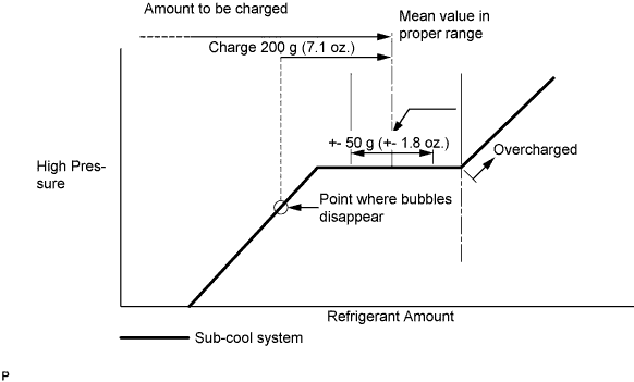
Standard Single A/C 520 to 580g (18.3 to 20.5 oz.) Dual A/C 670 to 730g (23.0 to 25.7 oz.) - SST
- 07110-58060 ( 07117-58090, 07117-78050, 07117-58070, 07117-58060, 07117-58080, 07117-88060, 07117-88070, 07117-88080 )
Note
-
Do not operate the cooler compressor before charging refrigerant as the cooler compressor does not work properly without any refrigerant, which causes the compressor to overheat.
-
Approximately 100 g (3.5 oz.) of refrigerant may need to be charged after bubbles disappear. The refrigerant amount should be checked by quantity, and not with the sight glass.
Tech Tips
Prepare a service can to recharge refrigerant if using the refrigerant gas collected with the freon collection/recycling device because the collective rate of the device is approximately 90%.
-
-
WARM UP ENGINE
-
Warm up the engine at less than 1,850 rpm for 2 minutes or more after charging refrigerant.
Note
Be sure to warm up the compressor when turning the A/C switch on after removing and installing the cooler refrigerant lines (including the compressor), to prevent damage to the compressor.
-
-
CHECK FOR ENGINE COOLANT LEAKS (2KD-FTV Type:)
CAUTION:
Do not remove the radiator cap while the engine and radiator are still hot. Pressurized, hot engine coolant and steam may be released and cause serious burns.
-
Fill the radiator with coolant and attach a radiator cap tester to the radiator.
-
Warm up the engine.
-
Using a radiator cap tester, increase the pressure inside the radiator to 137 kPa (1.4 kgf/cm2, 19.9 psi), and check that the pressure does not drop.
Tech Tips
If the pressure drops, check the hoses, radiator or water pump for leaks. If no external leaks are found, check the heater core, cylinder block and cylinder head.
-
-
CHECK FOR ENGINE COOLANT LEAKS (2TR-FE Type:)
CAUTION:
Do not remove the radiator cap while the engine and radiator are still hot. Pressurized, hot engine coolant and steam may be released and cause serious burns.
-
Fill the radiator with coolant and attach a radiator cap tester to the radiator.
-
Warm up the engine.
-
Using a radiator cap tester, increase the pressure inside the radiator to 137 kPa (1.4 kgf/cm2, 19.9 psi), and check that the pressure does not drop.
Tech Tips
If the pressure drops, check the hoses, radiator or water pump for leaks. If no external leaks are found, check the heater core, cylinder block and cylinder head.
-
-
CHECK FOR ENGINE COOLANT LEAKS (5L-E Type:)
CAUTION:
Do not remove the radiator cap while the engine and radiator are still hot. Pressurized, hot engine coolant and steam may be released and cause serious burns.
-
Fill the radiator with coolant and attach a radiator cap tester to the radiator.
-
Warm up the engine.
-
Using a radiator cap tester, increase the pressure inside the radiator to 118 kPa (1.2 kgf/cm2, 17.1 psi), and check that the pressure does not drop.
Tech Tips
If the pressure drops, check the hoses, radiator or water pump for leaks. If no external leaks are found, check the heater core, cylinder block, and cylinder head.
-
-
CHECK FOR LEAKAGE OF REFRIGERANT
-
After recharging refrigerant gas, check for leakage of refrigerant gas using a halogen leak detector.
-
Carry out the test under the following conditions:
-
Stop the engine.
-
Secure good ventilation (the gas leak detector may react to volatile gases which are not refrigerant, such as evaporated gasoline and exhaust gas).
-
Repeat the test 2 or 3 times.
-
Make sure that there is some refrigerant remaining in the refrigeration system.
When the compressor is off: approx. 392 to 588 kPa (4 to 6 kgf/cm2, 57 to 85 psi)
-
-
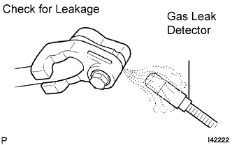
Using a gas leak detector, check for leakage of the refrigerant line.
-
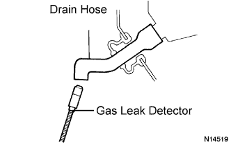
Bring the gas leak detector close to the drain hose with the detector's power off.
Tech Tips
-
After the blower motor has stopped, let the cooling unit stand for more than 15 minutes.
-
Bring the gas leak detector sensor under the drain hose.
-
When bringing the gas leak detector close to the drain hose, make sure that the gas leak detector does not react to volatile gases.
If such reaction is unavoidable, the vehicle must be lifted up.
-
-
If a gas leak is not detected on the drain hose, remove the blower motor control from the cooling unit. Insert the gas leak detector sensor into the unit and perform the test.
-
Disconnect the pressure switch connector and leave it for approximately 20 minutes. Bring the gas leak detector close to the pressure switch and perform the test.
-