AIR CONDITIONING UNIT REASSEMBLY

-
INSTALL EVAPORATOR TEMPERATURE SENSOR
-
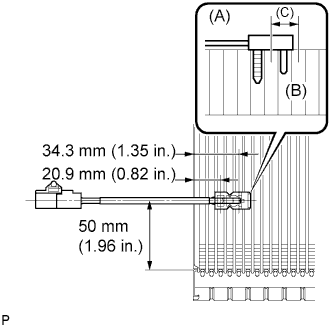
Install the sensor to the evaporator as shown in the illustration.
-
Check that the sensor sticks to the evaporator surface as shown in the illustration (A: Sensor, B: Evaporator).
Note
If reusing the evaporator, do not insert the sensor to the position that it had been inserted before. Insert it between position C shown in the illustration.
-
-
INSTALL COOLER EVAPORATOR SUB-ASSEMBLY NO.1
-
Sufficiently apply compressor oil (ND-OIL 8) to 2 new O-rings and the fitting surface. Install the 2 O-rings to the cooler evaporator No.1.
Compressor oil ND-OIL 8 or equivalent -
Install the cooler evaporator sub-assembly.
-
Install the connector.
-
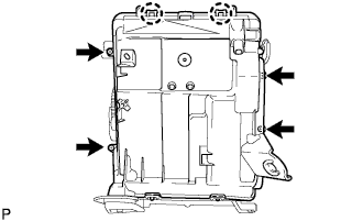
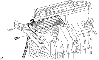
Install the heater case lower with the 2 claws and 4 screws.
-
-
INSTALL COOLER EXPANSION VALVE
-
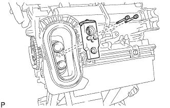
Using a hexagon wrench 4 mm, install the cooler expansion valve with the 2 hexagon bolts.
- Torque:
- 3.5 N*m { 35 kgf*cm, 30 in.*lbf }
-
-
INSTALL HEATER BRACKET
-
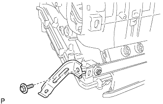
Install the heater bracket with the bolt.
-
-
INSTALL DRAIN COOLER HOSE
-
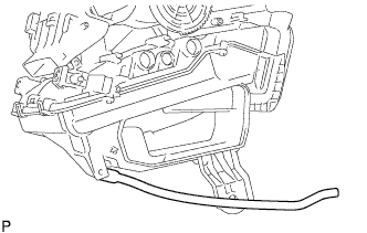
Install the drain cooler hose.
-
-
INSTALL AIR DUCT NO.3
-
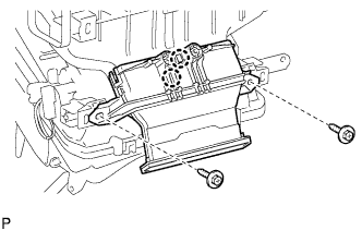
Engage the 2 claws to install the air duct No.3.
-
Install the 2 screws.
-
-
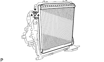
INSTALL HEATER RADIATOR UNIT SUB-ASSEMBLY
-
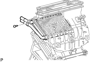
Install the heater radiator unit sub-assembly with the screw.
-
-
INSTALL QUICK HEATER ASSEMBLY (w/ PTC)
-
Install the quick heater assembly with the 2 screws.
-
-
INSTALL INSTRUMENT PANEL REGS CONNECTOR ASSEMBLY CENTER
-
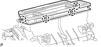
Engage the 4 claws to install instrument panel regs connector assembly.
-
-
INSTALL AIR MIX CONTROL CABLE
-
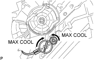
Fully turn the air mix control cable gear and unit gear in the direction indicated by the arrows to set them at "MAX. COOL".
-
Install the air mix control cable.
-
-
INSTALL MODE CONTROL CABLE
-
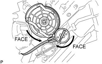
Fully turn the air mode control cable gear and unit link in the direction indicated by the arrows to set them at "FACE".
-
Install the mode control cable.
-