AIR CONDITIONING SYSTEM TERMINALS OF ECU

-
CHECK AIR CONDITIONING AMPLIFIER (1KD-FTV, 2KD-FTV, 2TR-FE)
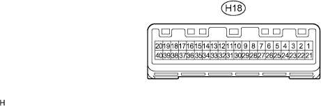
Symbols (Terminal No.) Wiring Color Tester Description Condition Specification PTC (H18-2) - GND (H18-29) LG - W-B PTC heater control signal Ignition switch: ON
Temperature switch: Max. HOT
Coolant temperature: Below 76°C (169°F)
Ambient temperature: Below 10°C (50°F)
PTC heater: Not operate → Operate (ALT, F-DUTY more than 95 %)
Below 1.0 V → 10 to 14 V PTCL (H18-3) - GND (H18-29) GR - W-B PTC heater permission signal Ignition switch: ON
Temperature switch: Max. HOT
Coolant temperature: Below 73°C (163°F)
Ambient temperature: Below 10°C (50°F)
PTC heater: Not operate → Operate (ALT, F-DUTY more than 95 %)
Below 1.0 V → 10 to 14 V PHTR (H18-5) - GND (H18-29) L-W - W-B Idle-up switch signal Ignition switch: ON
Idle-up switch: OFF → ON
Below 1.0 V → 10 to 14 V A.C (H18-8) - GND (H18-29) Y - W-B A/C switch signal Ignition switch: ON
Blower switch: ON
A/C switch: OFF → ON
Below 1.0 V → 10 to 14 V LED+ (H18-9) - GND (H18-29) G-B - W-B A/C switch indicator signal Ignition switch: ON
Blower switch: ON
A/C switch: OFF → ON
Below 1.0 V → 10 to 14 V BLW (H18-16) - GND (H18-29) L - W-B Blower motor control signal Ignition switch: ON
Blower switch: OFF → ON
10 to 14 V → Below 1.0 V GND (H18-29) - Body ground W-B - Body ground Ground for main power supply Always Below 1.0 Ω PRE (H18-4) - GND (H18-29) R-L - W-B A/C pressure sensor signal Start engine
Operate A/C system
Refrigerant pressure: Abnormal pressure (More than 3,030 kPa (31.0 kgf/cm, 440 psi))
4.7 V or higher PRE (H18-4) - GND (H18-29) R-L - W-B A/C pressure sensor signal Start engine
Operate A/C system
Refrigerant pressure: Abnormal pressure (less than 180 kPa (1.9 kgf/cm, 27 psi))
Below 0.7 V PRE (H18-4) - GND (H18-29) R-L - W-B A/C pressure sensor signal Start engine
Operate A/C system
Refrigerant pressure: Normal pressure (less than 3,030 kPa (31.0 kgf/cm, 440 psi) and more than 180 kPa (1.9 kgf/cm, 27 psi))
0.7 to 4.7 V S5 (H18-13) - SG-1 (H13-12) Y-R - L-W Power supply for pressure sensor Ignition switch: LOCK → ON Below 1.0 V → 5.15 V TAM (H18-25) - SG-1 (H13-12) G-W - L-W A/C ambient temperature sensor signal Ignition switch: LOCK → ON SG-1 (H18-12) - Body ground L-W - Body ground Ground for each sensor Always Below 1.0 Ω TE (H18-24) - SG (H18-31) W - L-B A/C evaporator temperature sensor signal Ignition switch: LOCK → ON SG (H18-31) - Body ground L-B - Body ground Ground for each sensor Always Below 1.0 Ω FRBV (H18-22) - SG (H18-31) L-R - LG-B Room compartment temperature set signal Max. HOT → Max. COOL 0 Ω → 3 kΩ MHSW (H18-38) - Body ground B-W - Body ground Max. hot switch signal Except max. HOT → Max. HOT Below 1.0 V → 10 to 14 V CANH (H18-10) - Body ground L - Body ground CAN communication system Ignition switch: LOCK → ON Pulse generation CANH (H18-11) - Body ground W - Body ground CAN communication system Ignition switch: LOCK → ON Pulse generation RRTE (H18-23) - SG-2 (H18-30) W-R - L-B Rear A/C evaporator temperature sensor signal Ignition switch: LOCK → ON SG-2 (H18-30) - Body ground L-B - Body ground Ground for rear A/C evaporator temperature sensor Always Below 1.0 Ω RRAC (H18-7) - Body ground P - Body ground Rear A/C switch signal Ignition switch: ON
A/C switch: OFF → ON
Below 1.0 V → 10 to 14 V RMGV (H18-18) - Body ground R-Y - Body ground Rear magnetic valve signal Ignition switch: ON
Rear magnetic valve: OFF → ON
10 to 14 V → Below 1.0 V LOCK (H18-28) - SG (H18-31) L - L-B Compressor lock sensor signal Engine idling
A/C switch: ON (Magnet clutch: ON)
Pulse generation
(see waveform 1)
MGC (H18-19) - Body ground R - Body ground Magnet clutch ON permission signal Ignition switch: ON
A/C switch: OFF → ON
10 to 14 V → Below 1.0 V IG+ (H18-20) - Body ground R-B - Body ground Power source (IG) Ignition switch: LOCK or ACC → ON Below 1.0 V → 10 to 14 V B (H18-40) - Body ground W-R - Body ground Power source (Back-up) Always 10 to 14 V -
CHECK AIR CONDITIONING AMPLIFIER (5L-E)

Symbols (Terminal No.) Wiring Color Tester Description Condition Specification AC1 (H19-8) - Body ground R-B - Body ground Compressor operation signal Ignition switch: ON
A/C switch: OFF → ON
3.7 to 4.5 V → 1.3 to 2.6 V ACT (H19-10) - Body ground G-W - Body ground Compressor permission signal Ignition switch: ON
A/C switch: OFF → ON
Below 1.0 V → 10 to 14 V A.C (H19-11) - GND (H19-6) Y - W-B A/C switch signal Ignition switch: ON
A/C switch: OFF → ON
Below 1.0 V → 10 to 14 V GND (H19-6) - Body ground W-B - Body ground Ground for main power supply Always Below 1.0 Ω PRE (H19-3) - Body ground R-L - Body ground A/C pressure switch signal Start engine
Operate A/C system
Refrigerant pressure: Normally → Less than 0.19 MPa (2.0 kgf/cm, 28 psi) or more than 1.34 MPa (13.7 kgf/cm, 195 psi))
Below 1 V → 10 to 14 V TE (H19-4) - SG (H19-16) W - L-B A/C evaporator temperature sensor signal Ignition switch: LOCK → ON SG (H19-16) - Body ground L-B - Body ground Ground for each sensor Always Below 1.0 Ω FRBV (H19-12) - SG (H19-16) B - L-B Room compartment temperature set signal Max. HOT → Max. COOL 0 Ω → 3 Ω RRTE (H19-7) - SG (H19-16) W-R - L-B Rear A/C evaporator temperature sensor signal Ignition switch: LOCK → ON RRAC (H19-18) - Body ground Y - Body ground Rear A/C switch signal Ignition switch: ON
A/C switch: OFF → ON
Below 1.0 V → 10 to 14 V RMGV (H19-9) - Body ground R-Y - Body ground Rear magnetic valve signal Ignition switch: ON
Rear magnetic valve: OFF → ON
Below 1.0 V → 10 to 14 V MGC (H19-15) - Body ground R - Body ground Magnet clutch ON permission signal Ignition switch: ON
A/C switch: OFF → ON
Below 1.0 V → 10 to 14 V IG+ (H19-13) - Body ground R-B - Body ground Power source (IG) Ignition switch: LOCK or ACC → ON Below 1.0 V → 10 to 14 V
-
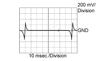
Waveform 1:
Measure the waveform between terminal LOCK of the A/C amplifier assembly connector and body ground.
-