STEERING COLUMN ASSEMBLY REMOVAL

-
DISCONNECT CABLE FROM NEGATIVE BATTERY TERMINAL
Note
Wait for 90 seconds after disconnecting the cable to prevent the airbag working.
-
PLACE FRONT WHEELS FACING STRAIGHT AHEAD
-
REMOVE STEERING PAD (w/o Airbag System)
-
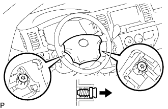
Using a "TORX" socket wrench (T30), loosen the 2 "TORX" screws until the groove along the screw circumference catches on the screw case.
-
Remove the steering pad.
-
Disconnect the horn connector.
-
-
REMOVE STEERING PAD (w/ Airbag System)
-
REMOVE NO. 2 STEERING WHEEL ORNAMENT (w/ Steering Wheel Ornament)
-
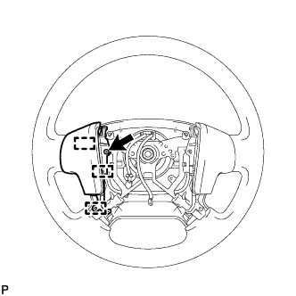
Remove the screw.
-
Detach the 3 guide pins and remove the steering No. 2 steering wheel ornament.
-
-
REMOVE NO. 1 STEERING WHEEL ORNAMENT (w/ Steering Wheel Ornament)
Tech Tips
Refer to the step "REMOVE NO. 2 STEERING WHEEL ORNAMENT (w/ Steering Wheel Ornament)".
-
REMOVE STEERING PAD SWITCH LH (w/ Steering Pad Switch)
-
Disconnect each connector.
-
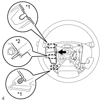
Text in Illustration *1 Pin *2 Guide Remove the screw.
-
Detach the 2 pins and guide and remove the steering pad switch LH.
-
-
REMOVE STEERING PAD COVER LH (w/o Steering Wheel Ornament)
-
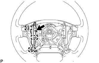
Remove the 2 screws.
-
Detach the 3 guide pins and remove the steering pad cover LH.
-
-
REMOVE STEERING PAD COVER RH (w/o Steering Wheel Ornament)
Tech Tips
Refer to the step "REMOVE STEERING PAD COVER LH (w/o Steering Wheel Ornament)".
-
REMOVE STEERING WHEEL ASSEMBLY
-
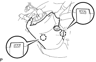
Remove the steering wheel set nut.
-
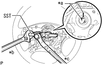
Text in Illustration *a Matchmark *b Hold *c Turn Put matchmarks on the steering wheel assembly and steering main shaft assembly.
-
Using SST, remove the steering wheel assembly.
- SST
- 09950-50013 ( 09951-05010, 09952-05010, 09953-05020, 09954-05021 )
Note
Apply a small amount of grease to the threads and tip of SST (09953-05020) before use.
-
-
REMOVE NO. 2 STEERING COLUMN LOWER COVER (w/ Smart Entry and Start System)
-
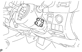
Detach the 4 claws and remove the No. 2 steering column lower cover.
-
-
REMOVE STEERING COLUMN LOWER COVER
Tech Tips
Adjust the position of the steering tilt mechanism when performing the procedure.
-
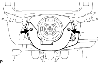
Remove the 2 "TORX" screws (T25) from the steering column lower cover.
-
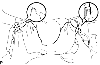
Push the steering column lower cover inward on both sides to detach the 2 claws.
-
Detach the 2 claws and remove the steering column lower cover.
-
-
REMOVE INSTRUMENT PANEL FINISH LOWER PANEL
-
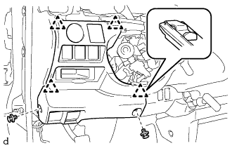
Using a clip remover, remove the 2 clips.
-
Detach the 4 clips and remove the instrument panel finish lower.
-
Disconnect each connector.
-
Push the positions indicated by the arrows in the illustration to disconnect the fuel lid lock control cable and bonnet (hood) control cable assembly from the instrument panel finish lower.
-
-
REMOVE STEERING COLUMN HOLE COVER
-
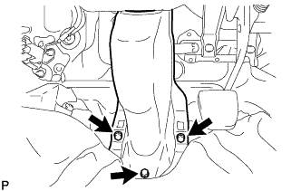
Remove the 3 bolts and the steering column hole cover.
-
-
DISCONNECT NO. 2 STEERING INTERMEDIATE SHAFT ASSEMBLY
-
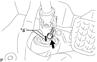
*a Matchmark Remove the bolt.
-
Slide the No. 2 steering intermediate shaft assembly and put matchmarks on the steering intermediate assembly and the No. 2 steering intermediate shaft assembly.
-
-
REMOVE STEERING COLUMN ASSEMBLY
-
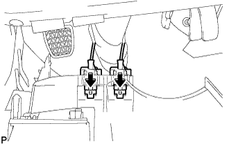
Disconnect the connectors and wire harness clamps from the steering column assembly.
-
Remove the 3 bolts and the steering column assembly.
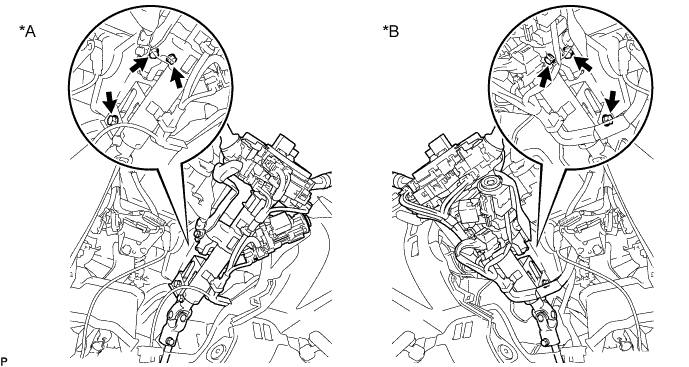
Text in Illustration *A LHD *B RHD Note
Make sure that the lever of the steering tilt mechanism is in the locked condition.
-
-
REMOVE STEERING COLUMN UPPER COVER
-
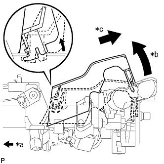
Text in Illustration *a Front of Vehicle *b Raise the backside of the steering column upper cover *c Pull diagonally backwards so that the claw of the steering column upper cover does not break Remove the steering column upper cover from the steering column assembly.
Note
If the steering column upper cover is removed by pulling it directly upwards, the claw may become damaged.
-
-
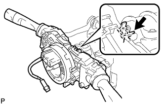
REMOVE TURN SIGNAL SWITCH WITH SPIRAL CABLE ASSEMBLY
-
w/o Smart Entry and Start System:
-
Use pliers to loosen the clamp, and then using a thin-bladed screwdriver, lift the claw upward and remove the turn signal switch with spiral cable assembly from the steering column assembly.
-
-
w/ Smart Entry and Start System:
-
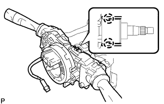
Using a thin-bladed screwdriver, detach the 2 claws and remove the turn signal switch with spiral cable assembly from the steering column assembly.
-
-