FRONT BRAKE DISASSEMBLY

-
REMOVE FRONT DISC BRAKE PAD KIT
-
Remove the 2 brake pads with anti-squeal shims.
-
-
REMOVE FRONT DISC BRAKE ANTI SQUEAL SHIM KIT
-
Remove the 4 anti-squeal shims from the brake pad.
-
Remove the pad wear indicator from each pad.
-
-
REMOVE FRONT DISC BRAKE PAD SUPPORT PLATE
-
REMOVE FRONT DISC BRAKE PAD SUPPORT PLATE
-
REMOVE FRONT DISC BRAKE CYLINDER SLIDE PIN
-
Remove the cylinder slide pin from the cylinder mounting.
-
-
REMOVE FRONT DISC BRAKE CYLINDER SLIDE BUSH
-
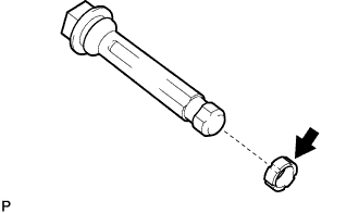
Using a screwdriver, remove the cylinder slide bush from the cylinder slide pin.
Tech Tips
Tape the screwdriver tip before use.
-
-
REMOVE FRONT DISC BRAKE CYLINDER SLIDE PIN NO.2
-
Remove the cylinder slide pin No.2 from the cylinder mounting.
-
-
REMOVE FRONT DISC BRAKE CYLINDER MOUNTING
-
Remove the 2 bolts and cylinder mounting.
-
-
REMOVE BUSH DUST BOOT NO.1
-
Secure the cylinder mounting in a vise.
-
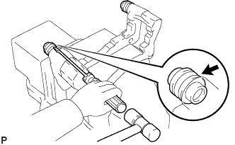
Using a screwdriver and a plastic hammer, remove the 2 bush dust boots.
-
-
REMOVE CYLINDER BOOT
-
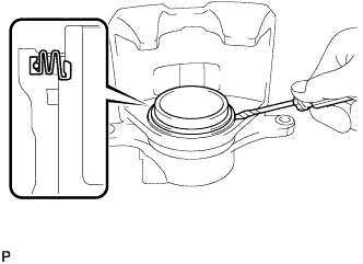
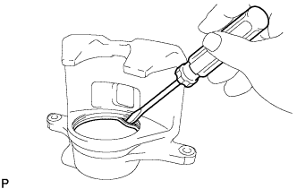
Using a screwdriver, remove the set ring.
Note
Do not damage the inner cylinder or cylinder groove.
Tech Tips
Tape the screwdriver tip before use.
-
Remove the cylinder boot.
-
-
REMOVE FRONT DISC BRAKE PISTON
-
Place a shop rag or a piece of cloth between the piston and the disc brake cylinder assembly.
-
Use compressed air to remove the piston from the disc brake cylinder assembly.
CAUTION:
Do not place your fingers in front of the piston when using compressed air.
Note
Do not spatter the brake fluid.
-
-
REMOVE PISTON SEAL
-
Using a screwdriver, remove the piston seal from the disc brake cylinder assembly.
Tech Tips
Tape the screwdriver tip before use.
-
-
REMOVE FRONT DISC BRAKE BLEEDER PLUG CAP
-
REMOVE FRONT DISC BRAKE BLEEDER PLUG
-
SEPARATE FRONT SPEED SENSOR
-
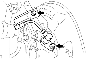
Remove the 2 bolts, and separate the speed sensor from the steering knuckle.
Note
-
Be careful not to damage the speed sensor.
-
Prevent foreign matter from adhering to the speed sensor.
-
-
-
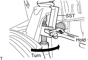
SEPARATE TIE ROD END SUB-ASSEMBLY
-
Remove the cotter pin and castle nut.
-
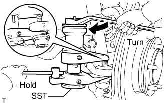
Using SST, separate the tie rod end from the steering knuckle.
- SST
- 09628-00011
Note
-
Do not damage the ball joint dust boot.
-
Do not damage the brake dust cover.
-
Make sure that the string of the SST is securely tied to the vehicle.
-
-
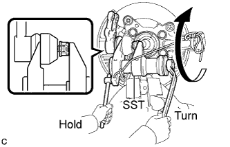
REMOVE FRONT AXLE ASSEMBLY
-
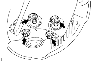
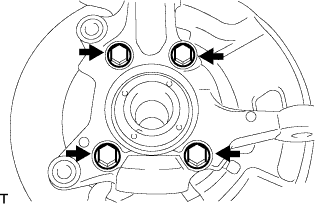
Remove the 4 bolts, 4 nuts and front axle assembly from the front suspension lower arm.
-
Remove the cotter pin and castle nut.
-
Using SST, remove the front axle assembly from the front suspension upper arm.
- SST
- 09628-62011
Note
-
Do not damage the ball joint dust boot.
-
Apply grease to the threads and tip of the SST center bolt before use.
-
Make sure that the string of the SST is securely tied to the vehicle.
-
-
REMOVE FRONT LOWER BALL JOINT ASSEMBLY
-
Fix the steering knuckle in the vise using aluminium plates.
Note
Do not damage the steering knuckle.
-
Remove the cotter pin.
-
Loosen the nut.
-
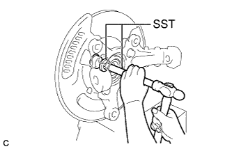
Using SST, separate the front lower ball joint assembly from the steering knuckle.
- SST
- 09628-00011
Note
-
Do not damage the ball joint dust boot.
-
Make sure that the string of the SST is securely tied to the steering knuckle.
-
Remove the nut and front lower ball joint assembly.
-
-
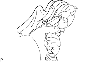
REMOVE INNER KNUCKLE GREASE RETAINER CAP (w/ Cap)
-
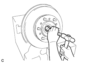
Using a chisel, make a hole in the center of the outer knuckle grease retainer cap to insert a brass bar.
-
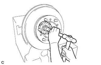
Using a brass bar, remove the inner knuckle grease retainer cap from the steering knuckle as shown in the illustration.
-
-
REMOVE OUTER KNUCKLE GREASE RETAINER CAP (w/ Cap)
-
Using SST, remove the outer knuckle grease retainer cap.
- SST
- 09950-60010 ( 09951-00300 )
- 09950-70010 ( 09951-07200 )
-
-
REMOVE STEERING KNUCKLE
-
Remove the 4 bolts.
-
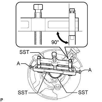
Using SST, remove the steering knuckle, brake dust cover from the front axle hub sub-assembly.
- SST
- 09950-40011 ( 09951-04020, 09952-04010, 09953-04010, 09958-04011 )
- 09950-60010 ( 09951-00470 )
- 09955-04140
- 09958-04030
Note
-
Apply grease to the threads and tip of the SST center bolt (09953-04010) before use.
-
Make sure that the slide arm (09952-04010) is at a 90° angle to the hanger 200 (09951-04020) when using SST.
-
Make sure that the claw No. 14 (09955-04140) is securely attached to the steering knuckle.
Tech Tips
For bolt A, use the bolt for the holder (09958-04011).
-
-
REMOVE FRONT DISC
-
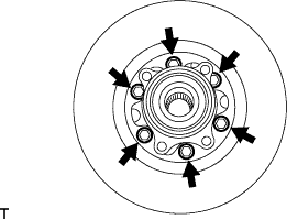
Remove the 6 bolts.
-
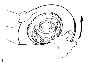
Remove the front disc as shown in the illustration.
-