BRAKE MASTER CYLINDER INSTALLATION

-
INSPECT AND ADJUST BRAKE BOOSTER PUSH ROD
Note
Adjust the brake booster assembly without vacuum. (Depress the brake pedal several times with engine stopped.)
Tech Tips
Adjustment of the brake booster push rod is performed when the brake master cylinder sub-assembly is replaced with a new one. The adjustment is not necessary when the brake booster assembly is replaced with a new one, but the brake master cylinder sub-assembly is reinstalled.
-
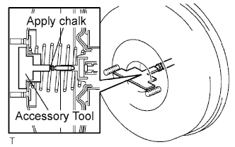
Apply chalk to the tip of the accessory tool.
Tech Tips
The accessory tool is enclosed with a new brake master cylinder sub-assembly.
-
Place the accessory tool on the brake booster assembly.
-
Measure the clearance between the brake booster push rod and accessory tool.
Clearance 0 mm (0 in.) Tech Tips
-
If there is clearance between the accessory tool and the shell of the brake booster (floating accessory tool), the clearance is too small.
-
If the chalk does not stick to the tip of the brake booster push rod, the clearance is too large.
Adjust the clearance in the following cases:
-
-
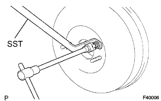
If clearance is not within the specified range, fix the push rod using SST and adjust the length of the protruding adjusting bolt.
- SST
- 09737-00020
Tech Tips
When adjusting the push rod, depress the brake pedal sufficiently so that the push rod sticks out.
-
-
INSTALL BRAKE MASTER LESS RESERVOIR TANK CYLINDER SUB-ASSEMBLY
-
Install the 2 grommets to the brake master cylinder reservoir.
-
Install the brake master cylinder reservoir with the retainer to the brake master cylinder.
Note
Check that the retainer is securely set.
-
-
INSTALL BRAKE MASTER CYLINDER
-
Install the brake master cylinder and harness clamp bracket to the booster with the 2 nuts.
- Torque:
- 12.7 N*m { 130 kgf*cm, 9 ft.*lbf }
Note
Check that the stopper of the harness clamp bracket is securely holding on the brake master cylinder assembly.
-
for Manual Transmission:
Install the clutch reservoir tube with the clip.
-
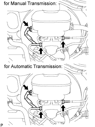
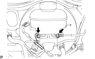
Using a union nut wrench, connect the 2 brake tubes to the master cylinder.
- Torque:
- 15 N*m { 155 kgf*cm, 11 ft.*lbf }
Note
Use the formula to calculate special torque values for situations where a union nut wrench is combined with a torque wrench Click here.
-
Connect the level warning light switch connector.
-
-
ADD BRAKE FLUID
Fluid SAE J1703 or FMVSS No. 116 DOT3 or equivalent -
BLEED BRAKE MASTER CYLINDER
Tech Tips
If the master cylinder has been disassembled or if the reservoir becomes empty, bleed the air from the master cylinder.
-
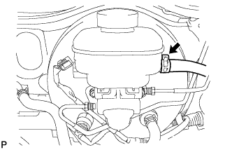
Using a union nut wrench, disconnect the brake lines from the master cylinder.
-
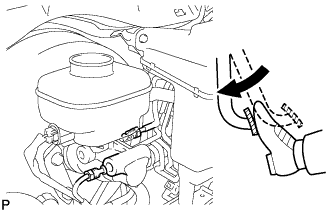
Slowly depress the brake pedal and hold it there.
-
Block the outer holes with your fingers, and release the brake pedal.
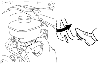
-
Remove your fingers. Slowly depress the brake pedal and hold it again. Block the outer holes with your fingers and release the brake pedal. Repeat this procedure 3 or 4 times.
-
Using a union nut wrench, connect the brake lines to the master cylinder.
- Torque:
- 15 N*m { 155 kgf*cm, 11 ft.*lbf }
Note
Use the formula to calculate special torque values for situations where a union nut wrench Click here.
-
-
BLEED BRAKE LINE
-
Connect the vinyl tube to the bleeder plug.
-
Depress the brake pedal several times and loosen the bleeder plug with the pedal held down.
-
At the point where the fluid stops coming out, tighten the bleeder plug and release the brake pedal.
-
Repeat this procedure until the air in the brake fluid is completely bled out.
-
Tighten the bleeder plug.
-
Front bleeder plug:
- Torque:
- 10.8 N*m { 110 kgf*cm, 8 ft.*lbf }
-
Rear bleeder plug:
- Torque:
- 11.0 N*m { 112 kgf*cm, 8 ft.*lbf }
-
-
Repeat the above procedure to bleed the air out of the brake line for each wheel.
-
-
CHECK BRAKE FLUID LEVEL
-
Check the fluid level and add fluid if necessary.
Fluid SAE J1703 or FMVSS No.116 DOT3 or equivalent
-
-
CHECK BRAKE FLUID LEAKAGE