BRAKE PEDAL INSTALLATION

-
TEMPORARILY TIGHTEN BRAKE PEDAL SUPPORT ASSEMBLY
-
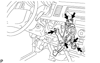
Using the 5 bolts and nut, temporarily install the brake pedal support assembly to the dash panel.
-
-
INSTALL ACCELERATOR PEDAL ROD ASSEMBLY
-
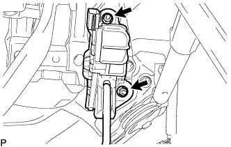
Install the accelerator pedal rod assembly with the 2 nuts.
- Torque:
- 5.0 N*m { 51 kgf*cm, 44 in.*lbf }
-
-
CONNECT WIRE HARNESS
-
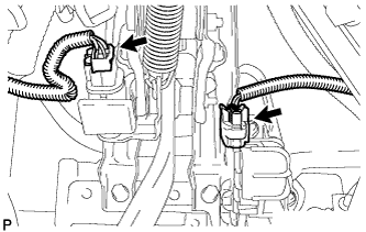
Connect the 2 connectors.
-
-
INSTALL BRAKE BOOSTER GASKET
-
INSTALL BRAKE BOOSTER ASSEMBLY
-
Install the brake booster assembly with the 4 nuts.
- Torque:
- 14 N*m { 145 kgf*cm, 10 ft.*lbf }
-
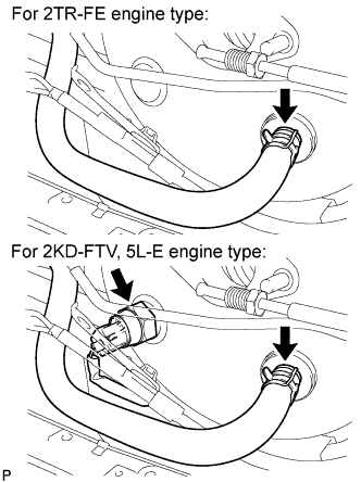
Connect the vacuum hose with the clip.
-
Fro 2KD-FTV, 5L-E engine type:
-
Connect the vacuum warning switch connector to the brake booster assembly.
-
-
-
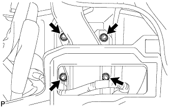
FULLY TIGHTEN BRAKE PEDAL SUPPORT ASSEMBLY
-
Fully tighten the 5 bolts and nut.
- Torque:
- 31 N*m { 316 kgf*cm, 23 ft.*lbf }
-
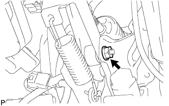
Fully tighten the nut.
- Torque:
- 34 N*m { 350 kgf*cm, 25 ft.*lbf }
-
-
INSTALL BRAKE TUBE
-
Automatic transmission:
-
Connect the 2 tubes to the clamp.
-
-
Manual transmission:
-
Connect the 3 tubes to the clamp.
-
Using SST, connect the clutch tube to the clutch master cylinder.
- SST
- 09023-00101
- Torque:
- 15 N*m { 155 kgf*cm, 11 ft.*lbf }
-
-
-
INSTALL MASTER CYLINDER PUSH ROD CLEVIS
-
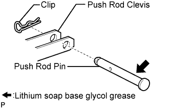
Apply lithium soap base glycol grease to the clevis pin.
-
Install the push rod clevis to the brake pedal support assembly with the clevis pin and a new clip.
-
-
INSTALL INSTRUMENT PANEL FINISH PANEL LOWER
-
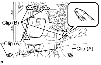
Engage the 4 clips (B).
-
Install the instrument panel finish panel lower with the 2 clips (A).
-
-
INSTALL HEADLIGHT ASSEMBLY LH (RHD (NARROW BODY TYPE))
Install of the headlight assembly RH is the same as the headlight assembly LH. Click here
-
INSTALL HEADLIGHT ASSEMBLY RH (RHD (WIDE BODY TYPE))
Install of the headlight assembly RH is the same as the headlight assembly LH. Click here
-
INSTALL AIR INLET DUCT NO.2 (LHD (W/ INTERCOOLER ASSEMBLY))
-
INSTALL AIR INLET DUCT NO.1 (LHD (W/ INTERCOOLER ASSEMBLY))
-
INSTALL RADIATOR SUPPORT SEAL UPPER (LHD (W/O INTERCOOLER ASSEMBLY))
-
INSTALL FRONT BUMPER SIDE SUPPORT RH (RHD (BODY TYPE WIDE))
-
INSTALL FRONT BUMPER COVER (RHD (BODY TYPE WIDE))
-
INSTALL STEP PLATE COVER RH (RHD (BODY TYPE WIDE))
-
INSTALL STEP PLATE COVER LH (RHD (BODY TYPE WIDE))
-
INSTALL RADIATOR GRILLE (W/O INTERCOOLER ASSEMBLY)
-
INSTALL BRAKE MASTER CYLINDER
-
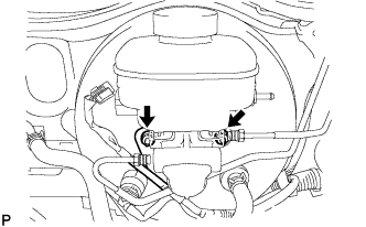
Install the brake master cylinder and harness clamp bracket to the booster with the 2 nuts.
- Torque:
- 12.7 N*m { 130 kgf*cm, 9 ft.*lbf }
Note
Check that the stopper of the harness clamp bracket is securely holding on the brake master cylinder assembly.
-
Manual Transmission:
-
Install the clutch reservoir tube with the clip.
-
-

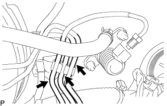
Using SST, connect the 2 brake tubes to the master cylinder.
- SST
- 09023-00101
- Torque:
- 15 N*m { 155 kgf*cm, 11 ft.*lbf }
-
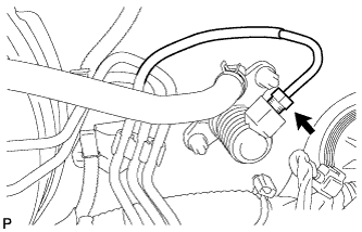
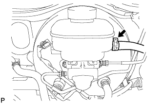
Connect the level warning light switch connector.
-
-
ADD BRAKE FLUID
-
BLEED BRAKE MASTER CYLINDER
Tech Tips
If the master cylinder has been disassembled or if the reservoir becomes empty, bleed the air from the master cylinder.
-
Using SST, disconnect the brake lines from the master cylinder.
- SST
- 09023-00101
-
Slowly depress the brake pedal and hold it there.
-
Block the outer holes with your fingers, and release the brake pedal.
-
Remove your fingers. Slowly depress the brake pedal and hold it again. Block the outer holes with your fingers and release the brake pedal. Repeat this procedure 3 or 4 times.
-
Using SST, connect the brake lines to the master cylinder.
- SST
- 09023-00101
- Torque:
- 15 N*m { 155 kgf*cm, 11 ft.*lbf }
-
-
BLEED BRAKE LINE
-
Connect the vinyl tube to the bleeder plug.
-
Depress the brake pedal several times and loosen the bleeder plug with the pedal held down.
-
At the point where the fluid stops coming out, tighten the bleeder plug and release the brake pedal.
-
Repeat this procedure until the air in the brake fluid is completely bled out.
-
Tighten the bleeder plug.
-
Front bleeder plug:
- Torque:
- 10.8 N*m { 110 kgf*cm, 8 ft.*lbf }
-
Rear bleeder plug:
- Torque:
- 11.0 N*m { 112 kgf*cm, 8 ft.*lbf }
-
-
Repeat the above procedure to bleed the air out of the brake line for each wheel.
-
-
INSPECT BRAKE FLUID LEVEL
-
Check the fluid level and add fluid if necessary.
Fluid SAE J1703 or FMVSS No.116 DOT3 or equivalent
-
-
INSPECT BRAKE FLUID
-
VEHICLE PREPARATION FOR HEADLIGHT AIM ADJUSTMENT
-
Prepare the vehicle:
-
Ensure that there is no damage or deformation to the body around the headlights.
-
Fill the fuel tank.
-
Make sure that the oil is filled to the specified level.
-
Make sure that the coolant is filled to the specified level.
-
Inflate the tires to the appropriate pressure.
-
Place the spare tire, tools, and jack in their original positions.
-
Unload the trunk.
-
Sit a person of average weight (75 kg, 165 lb) in the driver's seat.
-
-
-
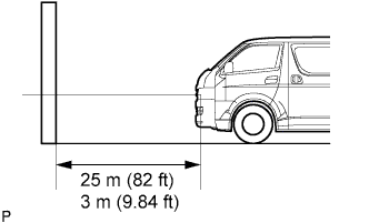
PREPARATION FOR HEADLIGHT AIMING (USING A SCREEN)
-
Prepare the vehicle according to the following conditions:
-
Place the vehicle in a location that is dark enough to clearly observe the cutoff line. The cutoff line is a distinct line, below which light from the headlights can be observed and above which it cannot.
-
Place the vehicle at a 90° angle to the wall.
-
Create a 25 m (82 ft) distance between the vehicle (headlight bulb center) and the wall.
-
Place the vehicle on a level surface.
-
Bounce the vehicle up and down to settle the suspension.
Note
A distance of 25 m (82 ft) between the vehicle (headlight bulb center) and the wall is necessary for proper aim adjustment. If unavailable, secure a distance of exactly 3 m (9.84 ft) for check and adjustment. (The target zone will change with the distance so follow the instructions in the illustration.)
-
-
Prepare a piece of thick white paper (approximately 2 m (6.6 ft) (height) x 4 m (13.1 ft) (width)) to use as a screen.
-
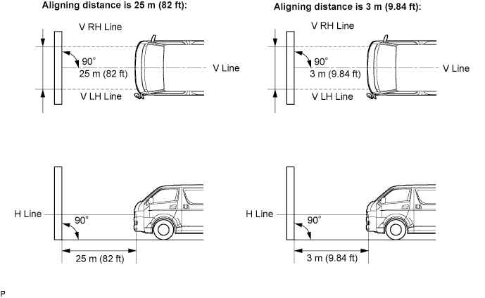
Draw a vertical line down the center of the screen (V line).
-
Set the screen as shown in the illustration.
Tech Tips
-
Stand the screen perpendicular to the ground.
-
Align the V line on the screen with the center of the vehicle.
-
-
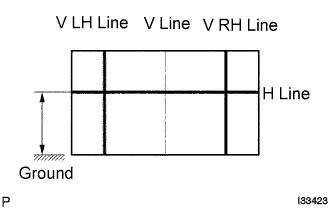
Draw base lines (H line, V LH, V RH lines) on the screen as shown in the illustration.
Tech Tips
-
The base lines differ for "low-beam inspection" and "high-beam inspection".
-
Make the headlight bulb center marks on the screen. If the center mark cannot be observed on the headlight, use the center of the headlight bulb or the manufacturer's name marked on the headlight as the center mark.
-
H Line (Headlight height):
-
Draw a horizontal line across the screen so that it passes through the center marks. The H line should be at the same height as the headlight bulb center marks of the low-beam headlights.
-
-
V LH Line, V RH Line (Center mark position of left-hand (LH) and right-hand (RH) headlights):
-
Draw two vertical lines so that they intersect the H line at each center mark (aligned with the center of the low-beam headlight bulbs).
-
-
-
-
HEADLIGHT AIMING INSPECTION
-
Cover or disconnect the connector of the headlight on the opposite side to prevent light from the headlight not being inspected from affecting headlight aiming inspection.
Note
Do not keep the headlight covered for more than 3 minutes. The headlight lens is made of synthetic resin, and may easily melt or be damaged due to heat.
Tech Tips
When checking the aim of the high-beam, cover the low-beam or disconnect the connector.
-
Start the engine.
Note
Engine rpm must be 1,500 or more.
-
With headlight leveling switch:
-
Set the headlight leveling switch to 0 (zero).
-
-
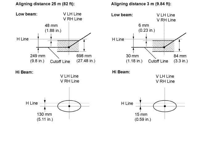
Turn on the headlight and make sure that the cutoff line falls within the specified area, as shown in the illustration.
Tech Tips
-
Alignment distance is 25 m (82 ft):
-
The cutoff line is 48 mm (1.88 in.) to 698 mm (27.48 in.) below the H line on low-beams (ECE Reg.48).
-
Alignment distance is 3 m (9.84 ft):
-
The cutoff line is 6 mm (0.23 in.) to 84 mm (3.3 in.) below the H line on low-beams (ECE Reg.48).
-
Alignment distance is 25 m (82 ft):
-
The cutoff line is 249 mm (9.8 in.) below the H line on low-beams.
-
Alignment distance is 3 m (9.84 ft):
-
The cutoff line is 30 mm (1.18 in.) below the H line on low-beams.
-
Since the low-beam light and the high-beam light are a unit, if the aim on one is correct, the other should also be correct. However, check both beams just to make sure.
-
-
-
ADJUST HEADLIGHT AIMING
-
Adjust the aim vertically:
-
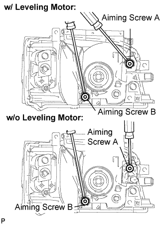
Adjust the headlight aim into the specified range by turning aiming screw A with a screwdriver.
Note
The final turn of the aiming screw should be made in the clockwise direction. If the screw is tightened excessively, loosen it and then retighten it, so that the final turn of the screw is in the clockwise direction.
Tech Tips
-
Perform low-beam aim adjustment.
-
The headlight aim moves up when turning the aiming screw clockwise, and moves down when turning the aiming screw counterclockwise.
-
-
Adjust the aim horizontally:
-
Adjust the headlight aim into the specified range by turning aiming screw B with a screwdriver.
Note
The final turn of the aiming screw should be made in the clockwise direction. If the screw is tightened excessively, loosen it and then retighten it, so that the final turn of the screw is in the clockwise direction.
Tech Tips
Perform low-beam aim adjustment.
-
-
-
INSPECT BRAKE PEDAL HEIGHT
-
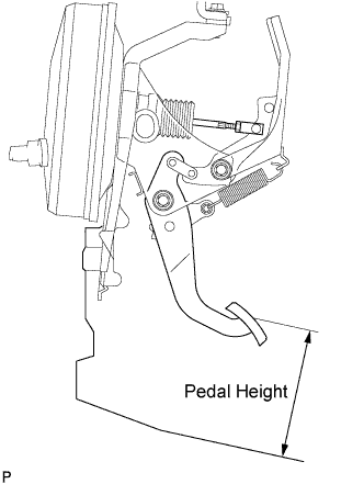
Check brake pedal height.
Pedal height from floor 151 to 161 mm (5.945 to 6.339 in.) for left hand drive 154 to 164 mm (6.063 to 6.457 in.) for right hand drive
-
-
ADJUST BRAKE PEDAL HEIGHT
-
Disconnect the stop light switch connector.
-
Turn the stop light switch assembly counter-clockwise and remove it.
-
Remove the brake booster Click here.
-
Loosen the push rod lock nut.
-
Adjust the pedal height by turning the pedal push rod clevis.
-
Tighten the push rod lock nut.
- Torque:
- 26 N*m { 260 kgf*cm, 19 ft.*lbf }
-
Install the brake booster Click here.
-
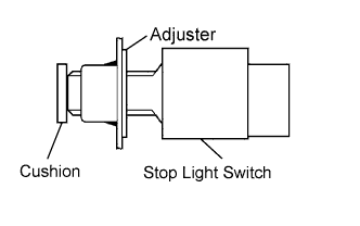
Insert the stop light switch into the adjuster until it slightly touches the cushion.
CAUTION:
Do not depress the brake pedal.
-
Turn the stop light switch assembly clockwise by approximately 90°.
CAUTION:
Do not depress the brake pedal.
-
Connect the stop light switch connector.
-
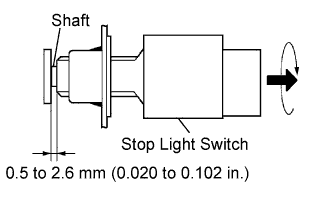
Check the clearance of the shaft.
Clearance 0.5 to 2.6 mm (0.020 to 0.102 in.)
-
-
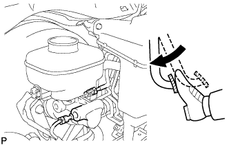
INSPECT BRAKE PEDAL FREE PLAY
-
Stop the engine and depress the brake pedal several times until there is no more vacuum left in the booster.
-
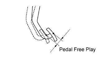
Push in the pedal until the beginning of the resistance is felt. Measure the distance as shown in the illustration.
Pedal free play 1.0 to 6.0 mm (0.039 to 0.236 in.)
-
-
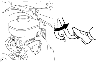
INSPECT BRAKE PEDAL RESERVE DISTANCE
-
Stop the engine and depress the brake pedal several times until there is no more vacuum left in the booster.
-
Release the parking brake handle.
-
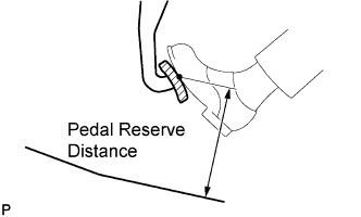
With the engine running, depress the pedal and measure the pedal reserve distance as shown in the illustration.
Pedal reserve distance from floor More than 117 mm (4.61 in.) at 500 N (51 kgf, 112.5 lbf) for left hand drive More than 120 mm (4.72 in.) at 500 N (51 kgf, 112.5 lbf) for right hand drive Note
Remove the floor mat before measuring the distance.
-