BRAKE ACTUATOR INSTALLATION

-
INSTALL BRAKE ACTUATOR ASSEMBLY
-
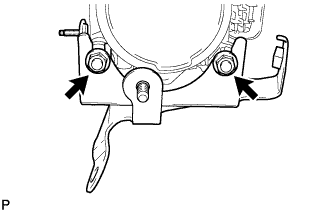
Install the brake actuator assembly to the actuator bracket with the 2 nuts.
- Torque:
- 5.4 N*m { 55 kgf*cm, 48 in.*lbf }
Note
-
Do not remove the hole plug until the new actuator assembly is connected because it already contains brake fluid.
-
Insert the protrusion of the actuator bolt holder between the positioning claws of the actuator bracket No.1.
-
Insert the positioning pin of the actuator bracket No.1 into the cushion of the actuator assembly.
-
-
INSTALL BRAKE ACTUATOR COVER
-
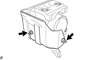
Install the actuator cover to the brake actuator assembly with the 2 nuts.
- Torque:
- 5.4 N*m { 55 kgf*cm, 48 in.*lbf }
-
-
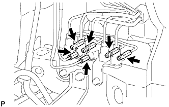
INSTALL BRAKE TUBE
-
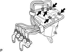
Using SST, install the 5 brake tubes and brake way No.1 to the brake actuator assembly.
- SST
- 09023-00101
- Torque:
- 15 N*m { 155 kgf*cm, 11 ft.*lbf }
-
-
INSTALL BRAKE ACTUATOR ASSEMBLY WITH FRONT BRAKE TUBE WAY NO.1
-
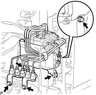
Install the brake actuator assembly with front brake tube way No.1 and the brake tube to the body with the 5 bolts.
- Torque:
- 20 N*m { 204 kgf*cm, 15 ft.*lbf }
Note
Do not bend or damage the brake tube.
-
Using SST, connect the 6 brake tubes to the front brake tube way No.1.
- SST
- 09023-00101
- Torque:
- 15 N*m { 155 kgf*cm, 11 ft.*lbf }
-
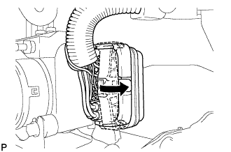
Connect the connector and lock the lock lever.
Note
Check that the lock lever is securely locked.
-
-
INSTALL FRONT MUDGUARD
-
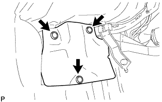
Install the front mudguard with the 3 clips.
-
-
INSTALL SUB RADIATOR ASSEMBLY
-
For 2KD-FTV Click here
-
For 5L-E Click here
-
-
INSTALL HIGH PITCHED HORN ASSEMBLY
-
INSTALL WINDSHIELD WASHER MOTOR AND PUMP ASSEMBLY
-
Connect the connector and hose.
-
Install the wind washer jar assembly with the 2 bolts.
- Torque:
- 4.9 N*m { 50 kgf*cm, 43 in.*lbf }
-
-
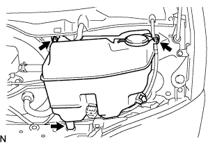
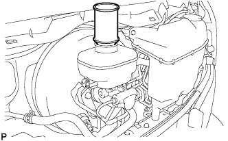
INSTALL RADIATOR RESERVE TANK ASSEMBLY
-
Connect the water by-pass hose No.2 with the clip.
-
Connect the water by-pass hose No.1 with the clip.
-
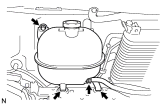
Place the reserve tank in the 2 grommets of the radiator upper support, and install the radiator reserve tank assembly with the bolt.
- Torque:
- 7.0 N*m { 71 kgf*cm, 62 in.*lbf }
-
-
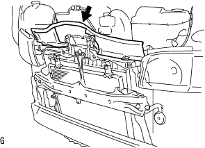
INSTALL RADIATOR SUPPORT UPPER
-
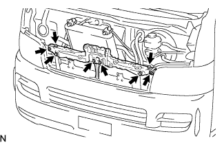
Install the radiator upper support with the 6 bolts and 2 screws.
- Torque:
- 5.5 N*m { 56 kgf*cm, 49 in.*lbf }
Tech Tips
If the position of the radiator upper support goes out of alignment while installing it, remove the front bumper and adjust the hood lock brace and bumper stay.
-
-
INSTALL HOOD LOCK ASSEMBLY
-
Connect the hood lock cable assembly to the hood lock assembly.
-
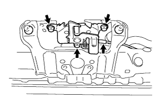
Temporarily tighten the hood lock assembly with the 3 bolts from the radiator upper support.
-
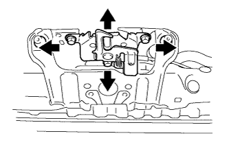
Check the hood position and adjust the hood lock assembly position.
-
Tighten the hood lock assembly with the 3 bolts.
- Torque:
- 12 N*m { 122 kgf*cm, 9 ft.*lbf }
-
-
INSTALL FRONT BUMPER REINFORCEMENT
-
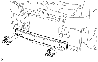
Install the front bumper reinforcement with the 6 bolts.
- Torque:
- 61 N*m { 622 kgf*cm, 45 ft.*lbf }
-
-
INSTALL HOOD LOCK SUPPORT BRACE SUB-ASSEMBLY
-
INSTALL AIR INLET DUCT NO.1 (LHD (W/ INTERCOOLER ASSEMBLY))
-
INSTALL AIR INLET DUCT NO.2 (LHD (W/ INTERCOOLER ASSEMBLY))
-
INSTALL RADIATOR SUPPORT SEAL UPPER (LHD (W/O INTERCOOLER ASSEMBLY))
-
Install the air inlet duct No.1 with the 6 clamps.
-
-
INSTALL FRONT BUMPER
-
INSTALL STEP PLATE COVER RH
-
INSTALL STEP PLATE COVER LH
-
INSTALL RADIATOR GRILLE
-
INSTALL ENGINE UNDER COVER NO.1
-
INSTALL FRONT WHEEL
- Torque:
- 100 N*m { 1,020 kgf*cm, 74 ft.*lbf }
-
ADD BRAKE FLUID
Fluid SAE J1703 or FMVSS No. 116 DOT3 or equivalent -
BLEED BRAKE LINE
-
Connect the vinyl tube to the bleeder plug.
-
Depress the brake pedal several times and loosen the bleeder plug with the pedal held down.
-
At the point where the fluid stops coming out, tighten the bleeder plug and release the brake pedal.
-
Repeat this procedure until the air in the brake fluid is completely bled out.
-
Tighten the bleeder plug.
-
Front bleeder plug:
- Torque:
- 10.8 N*m { 110 kgf*cm, 8 ft.*lbf }
-
Rear bleeder plug:
- Torque:
- 11.0 N*m { 112 kgf*cm, 8 ft.*lbf }
-
-
Repeat the above procedure to bleed the air out of the brake line for each wheel.
-
-
INSPECT BRAKE FLUID LEVEL
-
Check the fluid level and add fluid if necessary.
Fluid SAE J1703 or FMVSS No.116 DOT3 or equivalent
-
-
ADD ENGINE COOLANT
-
For 2TR-FE Click here
-
For 2KD-FTV Click here
-
For 5L-E Click here
-