ANTI-LOCK BRAKE SYSTEM TC and CG Terminal Circuit
DESCRIPTION
DTC output mode is set by connecting terminals TC and CG of the DLC3.
The DTCs are displayed by the blinking pattern of the ABS warning light.
WIRING DIAGRAM
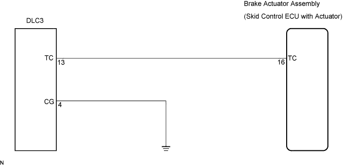
Tech Tips
When warning lights continue to blink, a ground short in the wiring of terminal TC of the DLC3 or an internal ground short in one or more ECU is suspected.
INSPECTION PROCEDURE
PROCEDURE
-
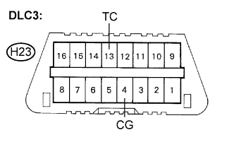
INSPECT DLC3 (BETWEEN DLC3 (TC) AND DLC3 (CG))
-
Turn the ignition switch to the ON position.
-
Measure the voltage according to the value(s) in the table below.
Standard voltage Tester Connection Specified Condition H23-13 (TC) - H23-4 (CG) 10 to 14 V
NG 
CHECK HARNESS AND CONNECTOR (BETWEEN DLC3 (CG) AND BODY GROUND) Click here
OK 
-
-
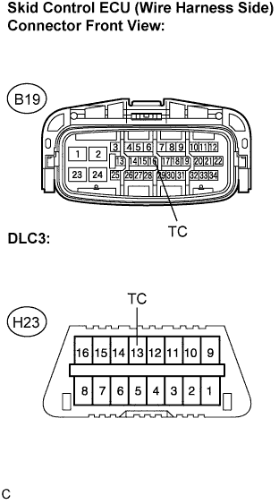
CHECK HARNESS AND CONNECTOR (BETWEEN SKID CONTROL ECU AND DLC3 (TC))
-
Turn the ignition switch off.
-
Disconnect the skid control ECU connector.
-
Measure the resistance according to the value(s) in the table below.
Standard resistance Tester Connection Specified Condition B19-16 (TC) - H23-13 (TC) Below 1 Ω B19-16 (TC) - Body ground 10 kΩ or higher
NG 
REPAIR OR REPLACE HARNESS OR CONNECTOR
OK 
REPLACE BRAKE ACTUATOR ASSEMBLY
-
-
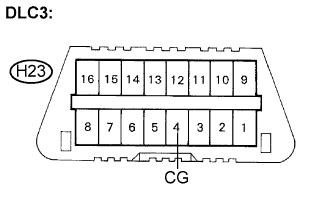
CHECK HARNESS AND CONNECTOR (BETWEEN DLC3 (CG) AND BODY GROUND)
-
Turn the ignition switch off.
-
Measure the resistance according to the value(s) in the table below.
Standard resistance Tester Connection Specified Condition H23-4 (CG) - Body ground Below 1 Ω
NG
REPAIR OR REPLACE HARNESS OR CONNECTOR
OK
-
-
CHECK HARNESS AND CONNECTOR (BETWEEN SKID CONTROL ECU AND DLC3 (TC))
-
Disconnect the skid control ECU connector.
-
Measure the resistance according to the value(s) in the table below.
Standard resistance Tester Connection Specified Condition B19-16 (TC) - H23-13 (TC) Below 1 Ω B19-16 (TC) - Body ground 10 kΩ or higher
NG
REPAIR OR REPLACE HARNESS OR CONNECTOR
OK
REPLACE BRAKE ACTUATOR ASSEMBLY
-