ANTI-LOCK BRAKE SYSTEM, Diagnostic DTC:C0273/13, C0274/14

| DTC Code | DTC Name |
|---|---|
| C0273/13 | Open in ABS Motor Relay Circuit |
| C0274/14 | Short to B+ in ABS Motor Relay Circuit |
DESCRIPTION
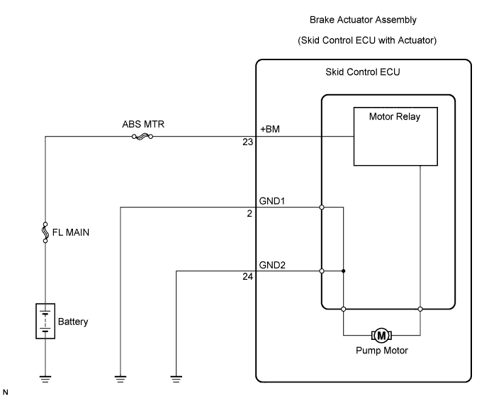
The ABS motor relay supplies power to the ABS pump motor. While the ABS is activated, the ECU turns the motor relay on and operates the ABS pump motor.
If the voltage supplied to the motor relay (+BM) is below the DTCs detection threshold due to low voltage from the battery/alternator, the DTCs may be stored.
| DTC No. | DTC Detection Condition | Trouble Area |
|---|---|---|
| C0273/13 | With the IG1 terminal voltage 9.5 V or more, the motor relay contact is OFF for 0.2 seconds or more immediately after the motor relay is turned ON. |
|
| C0274/14 | The motor contact is ON for 4 seconds or more when the motor relay is OFF. |
|
WIRING DIAGRAM
INSPECTION PROCEDURE
Tech Tips
After steps 1, 2 and 3 are completed, start the inspection from step 4 when using the intelligent tester, and from step 5 when not using the intelligent tester.
PROCEDURE
-
INSPECT FUSE (ABS MTR FUSE)
-
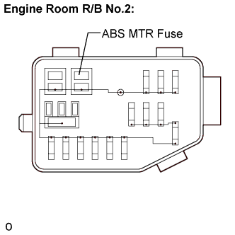
Remove the ABS MTR fuse from the engine room R/B No.2.
-
Measure the resistance according to the value(s) in the table below.
Standard resistance Tester Connection Specified Condition ABS MTR (40 A) fuse Below 1 Ω (Continuity)
NG 
REPLACE FUSE (ABS MTR FUSE)
OK 
-
-
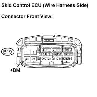
INSPECT SKID CONTROL ECU (+BM TERMINAL VOLTAGE)
-
Install the ABS MTR fuse.
-
Disconnect the skid control ECU connector.
-
Measure the voltage according to the value(s) in the table below.
Standard voltage Tester Connection Condition Specified Condition B19-23 (+BM) - Body ground Always 10 to 14 V
NG
REPAIR OR REPLACE HARNESS OR CONNECTOR (+BM CIRCUIT)
OK
-
-
INSPECT SKID CONTROL ECU (GND TERMINAL CONTINUITY)
-
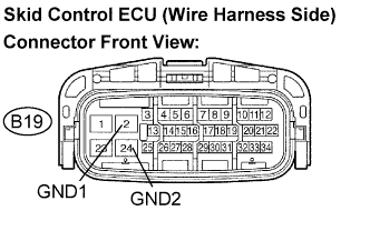
Measure the resistance according to the value(s) in the table below.
Standard resistance Tester Connection Specified Condition B19-2 (GND1) - Body ground Below 1 Ω B19-24 (GND2) - Body ground Below 1 Ω
NG
REPAIR OR REPLACE HARNESS OR CONNECTOR (GND CIRCUIT)
OK
-
-
PERFORM ACTIVE TEST USING INTELLIGENT TESTER (ABS MOTOR RELAY)
-
Reconnect the skid control ECU connector.
-
Connect the intelligent tester to the DLC3.
-
Turn the ignition switch to the ON position and turn the intelligent tester main switch on.
-
Start the engine.
-
Select the ACTIVE TEST mode on the intelligent tester.
ABS: Item (Display) Vehicle Condition / Test Details Diagnostic Note ABS Motor Relay Turns ABS motor relay ON / OFF Operating sound of motor is heard -
Check operating sound of the ABS motor when operating it with the intelligent tester.
OK The operating sound of the ABS motor is heard.
NG
REPLACE BRAKE ACTUATOR ASSEMBLY
OK
-
-
RECONFIRM DTC
-
Clear the DTCs Click here.
-
Start the engine.
-
Drive the vehicle at the speed of 4 mph (6 km/h) or more.
-
Check that the same DTCs are recorded Click here.
Tech Tips
-
Reinstall the sensors, connectors, etc. and restore the vehicle to its prior condition before rechecking for DTCs.
-
If a speed signal of 4 mph (6 km/h) or more is input to the skid control ECU, with the ignition switch on and the stop light switch off, the ECU performs self-diagnosis of the motor and solenoid circuits.
Result Condition Proceed to DTCs (C0273/13 and C0274/14) are output A DTCs (C0273/13 and C0274/14) are not output B Tech Tips
-
If any DTCs are output while jiggling a connector or wire harness of the brake actuator (skid control ECU), inspect and repair the connector or wire harness.
-
If the normal system code is output, slightly jiggle the connectors, wire harnesses, and fuses of the brake actuator assembly. Make sure that no DTCs are output.
-
These DTCs may be stored due to a malfunction in the connector terminal connection, etc.
-
B
END
A 
REPLACE BRAKE ACTUATOR ASSEMBLY
-