ANTI-LOCK BRAKE SYSTEM SYSTEM DESCRIPTION

-
SYSTEM DESCRIPTION
Tech Tips
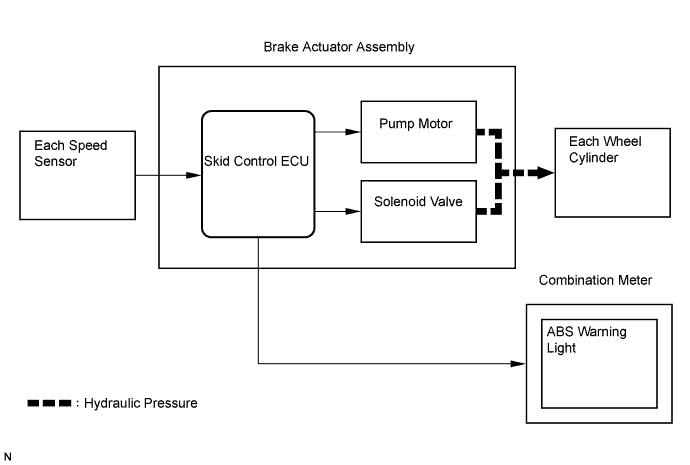
The skid control ECU is located within the brake actuator assembly.
-
ABS operation
-
Based on the signals received from the 4 wheel speed sensors, the skid control ECU calculates the speed of each wheel and deceleration, and checks wheel slipping condition. According to the slipping condition, the ECU controls the pressure holding valve and pressure reduction valve in order to adjust the fluid pressure of each wheel cylinder.
-
-
-
FUNCTION DESCRIPTION
-
ABS (Anti-lock Brake System)
The ABS helps prevent the wheels from locking when the brakes are applied firmly or when braking on a slippery surface.
-
Operation description
The skid control ECU detects a wheel lock condition by receiving vehicle speed signals from each speed sensor, and sends control signals to the pump motor and solenoid valve. The pump motor and solenoid valve prevent wheel lock by controlling the oil pressure of each wheel cylinder.
The ABS warning light comes on when the ABS system is malfunctioning.
-
-
BA (Brake Assist)
The primary purpose of the brake assist system is to provide and auxiliary brake force to assist the driver who cannot generate a large brake force during emergency braking, thus helping draw the vehicle's brake performance.
-
Operation description
The brake assist structure installed on the control valve of the brake booster determines an emergency brake based on the speed and the amount the brake pedal is depressed. This structure generates a strong braking force as needed.
-
-
-
FUNCTION COMPONENTS
Components Function Skid control ECU Judges the vehicle driving condition based on the signals from each sensor, and sends brake control signals to the brake actuator. Brake actuator assembly Changes the fluid path based on the signals from the skid control ECU during the operation of the ABS, in order to control the fluid pressure that is applied to the wheel cylinders. Motor relay Supply or cut off power to motor. Solenoid relay Supply or cut off power to solenoid valves. Speed sensor Detects the wheel speed of four wheels. Brake booster (with brake assist mechanism)
-
Increases the brake pedal effort.
-
Operates the brake assist mechanism to mechanically activate the brake assist function.
Stop light switch Detects the brake pedal depressing condition. Parking brake switch Detects that the parking brake lever is pulled. ABS warning light Lights up to alert the driver when the skid control ECU detects a malfunction in the ABS. -
-
FAIL SAFE
-
If a malfunction occurs in the signal system of the ABS system, the skid control ECU disables the ABS control.
-
-
INITIAL CHECK
-
After the ignition switch is turned to the ON position, and the vehicle attains an approximate speed of 4 mph (6 km/h) or more only at first time, the skid control ECU performs the initial check.
The functions of each solenoid valve and pump motor in the brake actuator are checked in order.
-