ANTI-LOCK BRAKE SYSTEM TEST MODE PROCEDURE

-
TEST MODE (SIGNAL CHECK) PROCEDURE (WHEN USING SST CHECK WIRE:)
Tech Tips
-
If the ignition switch is turned from the ON to the ACC or off position during Test Mode, the DTCs of the signal check function will be erased.
-
During Test Mode, the ECU records all the DTCs of the signal check function. By performing the signal check, the codes are erased if normality is confirmed. The remaining codes are the codes where an abnormality was found.
-
Turn the ignition switch off.
-
Check that the steering wheel is in the straight-ahead position and move the shift lever to the P position (Automatic Transmission) or apply the parking brake (Manual Transmission).
-
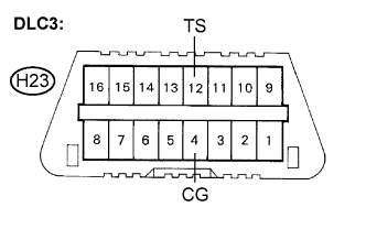
Using SST, connect terminals TS and CG of the DLC3.
- SST
- 09843-18040
-
Turn the ignition switch to the ON position.
-
After the ABS warning light comes on for several seconds, check if one of the following ECU codes is output.
Note
The ECU code is output only once each time the ignition switch is turned to the ON position.
ECU Code Floor Type Wheelbase 1 Standard Standard 2 Standard Long 5 Flat Standard -
Check that the ABS warning light starts to blink after the ECU code is indicated. This transition shows that the Test Mode is activated.
-
A blinking pattern of the ABS warning light (transition from ECU code 2 to Test Mode) is shown below as an example.
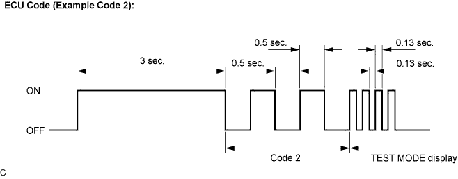
Tech Tips
If the output ECU code is incorrect, replace the brake actuator (skid control ECU) and then reactivate the Test Mode.
-
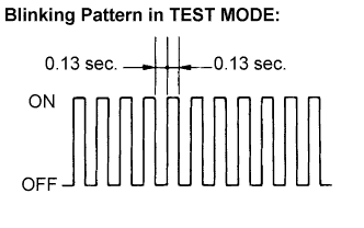
Check that the ABS warning light is blinking in the Test Mode.
Tech Tips
If the ABS warning light does not blink, inspect the TS and CG terminal circuit and the ABS warning light circuit.
Trouble Area See procedure TS and CG terminal circuit ABS warning light circuit -
Start the engine.
-
Using SST, perform the speed sensor signal check in Test Mode.
- SST
- 09843-18040
-
-
SPEED SENSOR SIGNAL CHECK
-
Check that the ABS warning light is blinking in Test Mode.
-
Drive the vehicle straight forward.
-
Accelerate the vehicle to a speed of 28 mph (45 km/h) or higher for several seconds and check that the ABS warning light goes off.
Tech Tips
The signal check may not be completed if the vehicle has its wheels spun.
-
Stop the vehicle.
Note
-
The speed sensor signal check may not be completed if the steering wheel is turned or the wheels are spun during the check.
-
After the ABS warning light goes off and if vehicle speed exceeds 50 mph (80 km/h), the signal check code will be stored again. Decelerate or stop the vehicle before the speed reaches 50 mph (80 km/h).
-
If the signal check has not been completed, the ABS warning light blinks while driving and the ABS system does not operate.
Tech Tips
When the signal check has been completed, the ABS warning light goes off while driving and blinks in the Test Mode pattern while stationary.
-
-
-
READ DTC
-
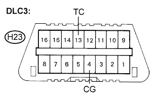
Using SST, connect terminals TC and CG of the DLC3.
- SST
- 09843-18040
-
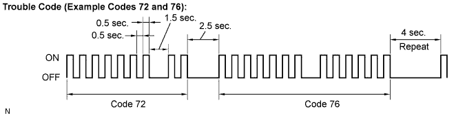
Read the number of blinks of the ABS warning light.
Tech Tips
-
See the list of DTC.
-
If every sensor is normal, the normal system code is output. (A cycle of 0.25 second ON and 0.25 second OFF is repeated.)
-
If more than 1 malfunction is detected at the same time, the lowest numbered code will be displayed first.
-
-
After performing the check, disconnect the SST from terminals TS and CG, TC and CG of the DLC3 and turn the ignition switch off.
-
-
DTC OF TEST MODE (SIGNAL CHECK) FUNCTION
Code No. Diagnosis Trouble Area C1271/71 Low output signal of front speed sensor RH
-
Front speed sensor RH
-
Sensor installation
-
Skid control rotor
C1272/72 Low output signal of front speed sensor LH
-
Front speed sensor LH
-
Sensor installation
-
Skid control rotor
C1273/73 Low output signal of rear speed sensor RH
-
Rear speed sensor RH
-
Sensor installation
-
Skid control rotor
C1274/74 Low output signal of rear speed sensor LH
-
Rear speed sensor LH
-
Sensor installation
-
Skid control rotor
C1275/75 Abnormal change in output signal of front speed sensor RH Skid control rotor C1276/76 Abnormal change in output signal of front speed sensor LH Skid control rotor C1277/77 Abnormal change in output signal of rear speed sensor RH Skid control rotor C1278/78 Abnormal change in output signal of rear speed sensor LH Skid control rotor Tech Tips
The codes in this table are output only in Test Mode (signal check).
-
-
TEST MODE (SIGNAL CHECK) PROCEDURE (WHEN USING INTELLIGENT TESTER:)
Tech Tips
-
If the ignition switch is turned from the ON to the ACC or LOCK position during Test Mode, DTCs of the signal check function will be erased.
-
During Test Mode, the ECU records all DTCs of the signal check function. By performing the signal check, the codes are erased if normality is confirmed. The remaining codes are the codes where an abnormality was found.
-
Turn the ignition switch off.
-
Check that the steering wheel is in the straight-ahead position and move the shift lever to the P position (Automatic Transmission) or apply the parking brake (Manual Transmission).
-
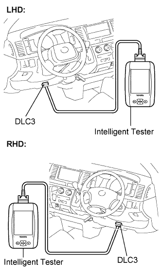
Connect the intelligent tester to the DLC3.
-
Turn the ignition switch to the ON position.
-
Set the intelligent tester to Test Mode (select "Signal Check").
Tech Tips
Refer to the intelligent tester operator's manual for further details.
-
After the ABS warning light comes on for several seconds, check if one of the following ECU codes is output.
Note
The ECU code is output only once each time the ignition switch is turned to the ON position.
ECU Code Floor Type Wheelbase 1 Standard Standard 2 Standard Long 5 Flat Standard -
Check that the ABS warning light starts to blink after the ECU code is indicated. This transition shows that the Test Mode is activated.
-
A blinking pattern of the ABS warning light (transition from ECU code 2 to Test Mode) is shown below as an example.
Tech Tips
If the output ECU code is incorrect, replace the brake actuator (skid control ECU) and then reactivate the Test Mode.
-
Check that the ABS warning light is blinking in the Test Mode.
Tech Tips
If the ABS warning light does not blink, inspect the TS and CG terminal circuit and the ABS warning light circuit.
Trouble Area See procedure TS and CG terminal circuit ABS warning light circuit -
Start the engine.
-
Using the intelligent tester, perform the speed sensor signal check in Test Mode.
-
-
SPEED SENSOR SIGNAL CHECK
-
Check that the ABS warning light is blinking in Test Mode.
-
Drive the vehicle straight forward.
-
Accelerate the vehicle to a speed of 28 mph (45 km/h) or higher for several seconds and check that the ABS warning light goes off.
Tech Tips
The signal check may not be completed if the vehicle has its wheels spun.
-
Stop the vehicle.
Note
-
The speed sensor signal check may not be completed if the steering wheel is turned or the wheels are spun during the check.
-
After the ABS warning light goes off and if vehicle speed exceeds 50 mph (80 km/h), a signal check code will be stored again. Decelerate or stop the vehicle before the speed reaches 50 mph (80 km/h).
-
If the signal check has not been completed, the ABS warning light blinks while driving and the ABS system does not operate.
Tech Tips
When the signal check has been completed, the ABS warning light goes off while driving and blinks in the Test Mode pattern while stationary.
-
-
-
READ DTC
-
Read the DTC(s) by following the tester screen.
Tech Tips
-
Refer to the intelligent tester operator's manual for further details.
-
See the list of DTC.
-
-
-
DTC OF TEST MODE (SIGNAL CHECK) FUNCTION
Code No. Diagnosis Trouble Area C1271/71 Low output signal of front speed sensor RH
-
Front speed sensor RH
-
Sensor installation
-
Skid control rotor
C1272/72 Low output signal of front speed sensor LH
-
Front speed sensor LH
-
Sensor installation
-
Skid control rotor
C1273/73 Low output signal of rear speed sensor RH
-
Rear speed sensor RH
-
Sensor installation
-
Skid control rotor
C1274/74 Low output signal of rear speed sensor LH
-
Rear speed sensor LH
-
Sensor installation
-
Skid control rotor
C1275/75 Abnormal change in output signal of front speed sensor RH Skid control rotor C1276/76 Abnormal change in output signal of front speed sensor LH Skid control rotor C1277/77 Abnormal change in output signal of rear speed sensor RH Skid control rotor C1278/78 Abnormal change in output signal of rear speed sensor LH Skid control rotor Tech Tips
The codes in this table are output only in Test Mode (signal check).
-