REAR DIFFERENTIAL CARRIER ASSEMBLY INSTALLATION

-
INSTALL REAR DIFFERENTIAL CARRIER GASKET
-
Install a new differential carrier gasket to the rear axle housing assembly.
-
-
INSTALL REAR DIFFERENTIAL CARRIER ASSEMBLY
-
Clean the contact surfaces of the differential carrier assembly and the rear axle housing assembly.
-
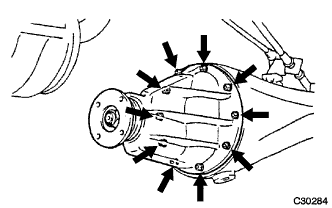
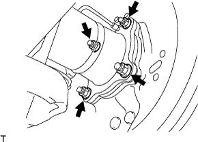
Install the differential carrier assembly with the 10 nuts and washers.
- Torque:
- 25 N*m { 255 kgf*cm, 18 ft.*lbf }
-
-
INSTALL LOAD SENSING BRACKET
-
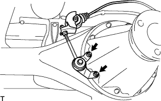
Install the load sensing bracket with the 2 nuts.
- Torque:
- 13 N*m { 133 kgf*cm, 10 ft.*lbf }
-
-
INSTALL REAR AXLE HOUSING DRAIN PLUG
-
Install the drain plug with a new gasket.
- Torque:
- 49 N*m { 500 kgf*cm, 36 ft.*lbf }
-
-
INSTALL PROPELLER SHAFT ASSEMBLY (for Super Long Wheelbase)
-
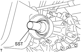
Remove the SST from the extension housing.
-
Install the propeller with center bearing shaft assembly in the extension housing.
-
Install the center support bearing assembly No.1, and temporarily tighten the 2 bolts.
-
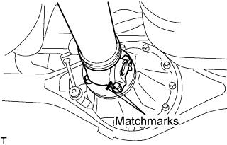
Align the matchmarks on the propeller shaft flange and differential flange.
-
Install the propeller shaft assembly with the 4 nuts, 4 bolts and 4 washers.
- Torque:
- 74 N*m { 755 kgf*cm, 54 ft.*lbf }
-
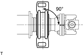
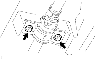
Check that the center line of the bracket is at right angles to the shaft axial direction.
-
Adjust the center support bearing assembly No.1.
Tech Tips
-
With the vehicle unladen, adjust the center support bearing No.1 to maintain the angles, as shown.
-
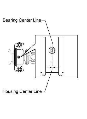
In the same conditions, check the center line in the axial direction. Adjust the bearing if necessary.
-
The center bearing center line and center bearing housing center line must be adjusted to within -1.0 to 1.0 mm (-0.0394 to 0.0394 in.) of each other in the vehicle's longitudinal direction with the vehicle unladen.
-
-
Tighten the 2 bolts.
- Torque:
- 36 N*m { 369 kgf*cm, 27 ft.*lbf }
-
-
INSTALL PROPELLER SHAFT ASSEMBLY (for Long Wheelbase)
-
Remove the SST from the extension housing.
-
Install the propeller shaft assembly in the extension housing.
-
Align the matchmarks on the propeller shaft flange and differential flange.
-
Install the propeller shaft assembly with the 4 nuts, 4 bolts and 4 washers.
- Torque:
- 74 N*m { 755 kgf*cm, 54 ft.*lbf }
-
-
INSTALL REAR AXLE SHAFT LH OIL SEAL
-
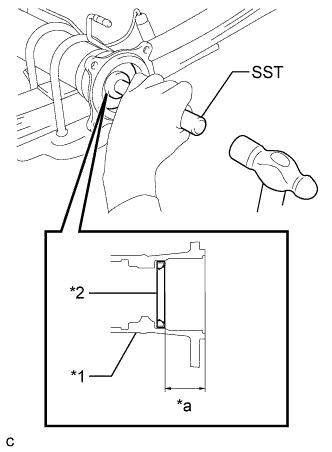
Text in Illustration *1 Rear Axle Housing Assembly *2 Rear Axle Shaft Oil Seal *a Seal installation depth Using SST and a hammer, install a new rear axle shaft oil seal.
- SST
- 09554-22010
Seal installation depth 34.5 to 35.5 mm (1.358 to 1.398 in.) Note
-
Do not drive the oil seal in deeper than the specified range or an oil leak will occur.
-
Do not tilt the oil seal during installation.
-
Apply MP grease to the oil seal lip.
-
-
INSTALL REAR AXLE SHAFT RH OIL SEAL
Tech Tips
Installation procedure of the RH side is the same as that of the LH side.
-
INSTALL BEARING RETAINER O-RINGS
-
Apply MP grease to the bearing retainer O-ring.
-
Install the bearing retainer O-ring to the rear axle shaft housing.
-
-
INSTALL REAR AXLE SHAFT WITH BACKING PLATE LH
-
Install the rear axle shaft with backing plate to the rear axle shaft housing with the 4 nuts.
- Torque:
- 65 N*m { 663 kgf*cm, 48 ft.*lbf }
Note
-
Be careful not to damage the rear axle shaft oil seal.
-
Be careful not to damage the skid control rotor rear.
-
-
REMOVE REAR AXLE SHAFT WITH BACKING PLATE RH
Tech Tips
Installation procedure of the RH side is the same as that of the LH side.
-
INSTALL SPEED SENSOR REAR LH (w/ ABS)
-
Install the rear speed sensor LH with the bolt.
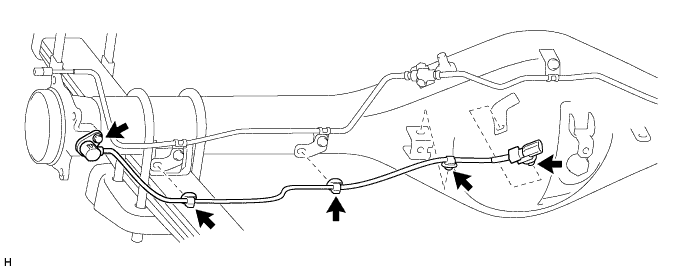
- Torque:
- 8.5 N*m { 87 kgf*cm, 75 in.*lbf }
Note
Prevent foreign matter from attaching to the sensor tip.
-
Attach the 4 clamps.
-
Connect the connector.
-
-
INSTALL SPEED SENSOR REAR RH (w/ ABS)
Tech Tips
Installation procedure of the RH side is the same as that of the LH side.
-
INSTALL REAR WHEEL BRAKE CYLINDER ASSEMBLY LH
-
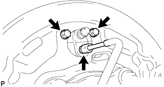
Install the wheel brake cylinder assembly with the 2 bolts.
- Torque:
- 9.5 N*m { 97 kgf*cm, 84 in.*lbf }
-
Using a union nut wrench, connect the brake tube.
- Torque:
- 15 N*m { 155 kgf*cm, 11 ft.*lbf }
Note
Use the formula to calculate special torque values for situations where a union nut wrench is combined with a torque wrench Click here.
-
-
INSTALL REAR WHEEL BRAKE CYLINDER ASSEMBLY RH
Tech Tips
Installation procedure of the RH side is the same as that of the LH side.
-
APPLY HIGH TEMPERATURE GREASE
-
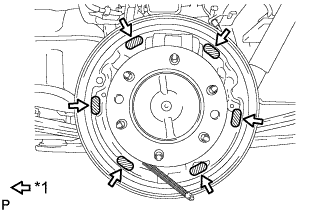
Text in Illustration *1 High temperature grease Apply high temperature grease to the shoe attached surface of the backing plate.
-
-
CONNECT PARKING BRAKE CABLE ASSEMBLY NO. 3
-
Install the parking brake cable assembly No.3 to the rear brake backing plate with the 2 bolts.
- Torque:
- 8.0 N*m { 82 kgf*cm, 71 in.*lbf }
-
-
CONNECT PARKING BRAKE CABLE ASSEMBLY NO. 2
Tech Tips
Installation procedure of the RH side is the same as that of the LH side.
-
INSTALL PARKING BRAKE SHOE STRUT SET LH
-
for 254 mm drum:
-
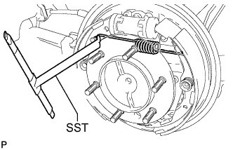
Using SST, install the upper side tension spring.
- SST
- 09703-30011
-
-
for 295 mm drum:
-
Using SST, install the upper side tension spring.
- SST
- 09703-30011
-
-
-
INSTALL PARKING BRAKE SHOE STRUT SET RH
Tech Tips
Installation procedure of the RH side is the same as that of the LH side.
-
INSTALL REAR BRAKE SHOES
-
for 254 mm drum:
-
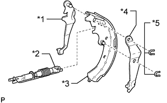
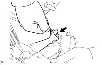
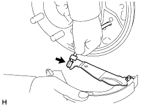
Text in Illustration *1 Brake Shoe Lever *2 Brake Shoe Strut Set *3 Rear Brake Shoe *4 Rear Cushion Lever *5 C-washer Using pliers, install the rear brake shoe, shoe strut set, rear cushion lever and shoe lever with a new C-washer.
-
Connect the parking brake cable No. 3 to the front brake shoe.
-
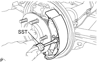
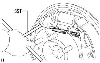
Using SST, install the rear brake shoe, pin, shoe hold down spring and shoe hold down cup.
- SST
- 09718-00011
-
-
for 295 mm drum:
-
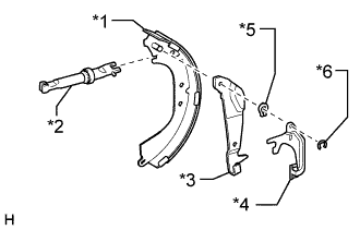
Text in Illustration *1 Rear Brake Shoe *2 Brake Shoe Strut Set *3 Brake Shoe Lever *4 Automatic Adjust Lever *5 C-washer *6 E-ring Install the rear brake shoe, brake shoe strut set and shoe lever with a new C-washer.
-
Install a new E-ring and the automatic adjust lever.
-
Connect the parking brake cable No. 3 to the front brake shoe.
-
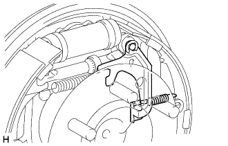
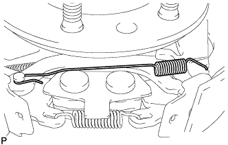
Install the tension spring as shown in the illustration.
-
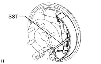
Using SST, install the rear brake shoe, pin, shoe hold down spring and shoe hold down cup.
- SST
- 09718-00011
-
-
-
INSTALL FRONT BRAKE SHOES
-
for 254 mm from:
-
Install the return spring to each brake shoe.
-
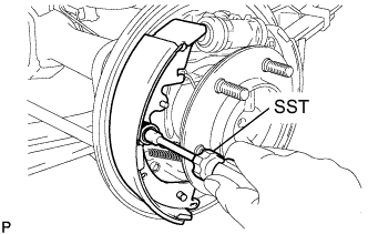
Using SST, install the front brake shoe, pin, shoe hold down spring and shoe hold down cup.
- SST
- 09718-00011
-
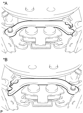
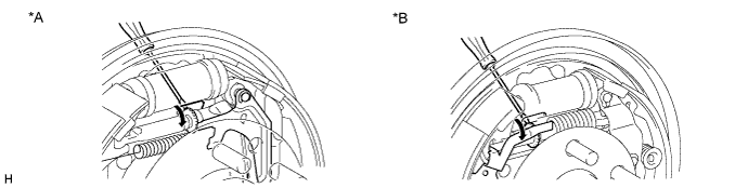
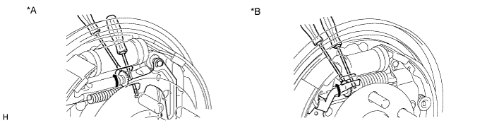
Text in Illustration *A LH Side *B RH Side Install the brake shoe lower strut.
Note
Make sure that the shoe lower strut and brake rear cushion lever are securely engaged.
-
Using needle-nose pliers, install the tension spring.
-
-
for 295 mm drum:
-
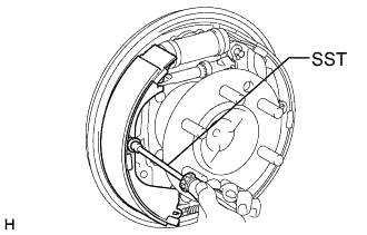
Using SST, install the front brake shoe, pin, shoe hold down spring and shoe hold down cup.
- SST
- 09718-00011
-
Install the return spring to each brake shoe.
-
-
-
CONNECT PARKING BRAKE SHOE STRUT SET LH
-
for 254 mm drum:
-
Using SST, install the upper side tension spring.
- SST
- 09703-30011
-
-
for 295 mm drum:
-
Using SST, install the upper side tension spring.
- SST
- 09703-30011
-
-
-
CONNECT PARKING BRAKE SHOE STRUT SET RH
Tech Tips
Installation procedure of the RH side is the same as that of the LH side.
-
INSTALL AUTOMATIC ADJUST LEVER LH
-
for 254 mm drum:
-
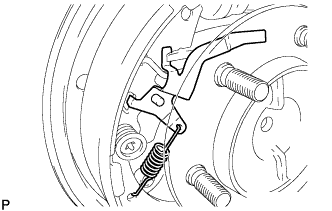
Install the automatic adjust lever and tension spring.
Note
Make sure to install the automatic adjust lever between the groove of the shoe strut set and brake shoe.
-
-
-
INSTALL AUTOMATIC ADJUST LEVER RH
Tech Tips
Installation procedure of the RH side is the same as that of the LH side.
-
INSPECT REAR DRUM BRAKE
-
Check the each part is installed properly.
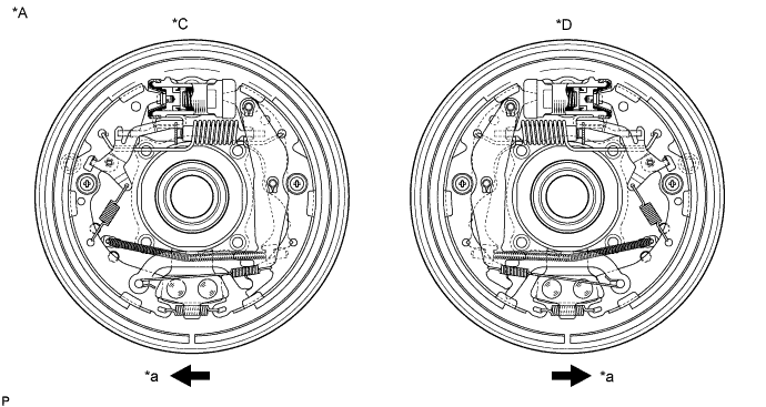
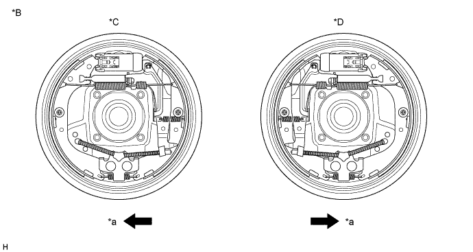
Text in Illustration *A for 254 mm Drum *B for 295 mm Drum *C LH Side *D RH Side *a Front - - Note
There should be no oil or grease adhering to the friction surfaces of the shoe lining and drum.
-
If they are not installed correctly, reinstall them as shown in the illustration.
-
-
INSTALL REAR AXLE BRAKE DRUM GASKETS
-
Install the new brake drum gasket to the rear axle shaft.
-
-
INSTALL REAR BRAKE DRUM SUB-ASSEMBLIES
-
ADJUST REAR DRUM BRAKE SHOE CLEARANCE
-
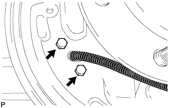
Using a screwdriver from a service hole, turn the adjuster to expand the shoes so that the brake shoes touch the brake drum.
Text in Illustration *A for 295 mm Drum *B for 254 mm Drum -
Using another screwdriver, push up the automatic adjust lever and turn the adjuster to contract the shoes so that the brake shoe does not touch the brake drum. Then turn the adjuster another 180 degrees to further contract the shoes.
Text in Illustration *A for 295 mm Drum *B for 254 mm Drum -
Install the hole plug.
-
-
ADD BRAKE FLUID
Fluid SAE J1703 or FMVSS No. 116 DOT3 or equivalent -
BLEED BRAKE LINE
-
Connect the vinyl tube to the bleeder plug.
-
Depress the brake pedal several times and loosen the bleeder plug with the pedal held down.
-
At the point where the fluid stops coming out, tighten the bleeder plug and release the brake pedal.
-
Repeat this procedure until the air in the brake fluid is completely bled out.
-
Tighten the bleeder plug.
-
Front bleeder plug:
- Torque:
- 10.8 N*m { 110 kgf*cm, 8 ft.*lbf }
-
Rear bleeder plug:
- Torque:
- 11.0 N*m { 112 kgf*cm, 8 ft.*lbf }
-
-
Repeat the above procedure to bleed the air out of the brake line for each wheel.
-
-
INSPECT BRAKE FLUID LEVEL
-
Check the fluid level and add fluid if necessary.
Fluid SAE J1703 or FMVSS No.116 DOT3 or equivalent
-
-
FILL DIFFERENTIAL OIL
-
Remove the differential filler plug and gasket.
-
Fill with oil.
Oil grade Hypoid gear oil API GL-5 or equivalent Recommended oil viscosity Above -18°C (0°F) SAE 90 Below -18°C (0°F) SAE 80W or 80W-90 -
Check the oil level.
-
Install the differential filler plug with a new gasket.
- Torque:
- 49 N*m { 500 kgf*cm, 36 ft.*lbf }
Note
After replacing the oil, recheck the oil level after driving.
-
-
INSPECT AND ADJUST DIFFERENTIAL OIL
-
Stop the vehicle on a level place.
-
Remove the differential filler plug and gasket.
-
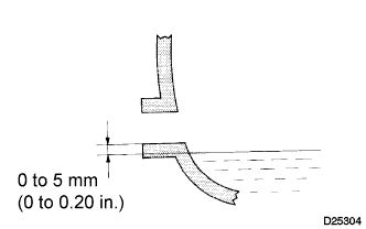
Check that the oil surface is within 5 mm (0.20 in.) of the lowest position of the inner surface of the differential filler plug opening.
Note
-
Excessively large or small amounts of oil may cause trouble.
-
After replacing oil, drive the vehicle and check the oil level.
Tech Tips
If necessary, fill the rear differential carrier with hypoid gear oil.
-
-
Check for oil leakage when the oil level is low.
-
Install the differential filler plug and a new gasket.
- Torque:
- 49 N*m { 500 kgf*cm, 36 ft.*lbf }
-
-
INSTALL REAR WHEELS
- Torque:
- 100 N*m { 1,020 kgf*cm, 74 ft.*lbf }
-
INSPECT PARKING BRAKE CONTROL HANDLE TRAVEL
-
Pull firmly on the parking brake control handle.
-
Release the parking brake lock, and return the parking brake control handle to its off position.
-
Slowly pull the parking brake control handle all the way up, and count the number of clicks.
Parking brake control handle travel 10 to 16 clicks at 200 N (20 kgf, 44 lbf) Tech Tips
-
If the number of clicks falls outside of the specified range, release the parking brake lock and adjust it.
-
If there are fewer clicks than the specified value, loosen the parking brake wire adjustment nut an the lock nut. With the parking brake cable loosened, adjust the clearance between the brake drum and lining.
-
-
-
ADJUST PARKING BRAKE CONTROL HANDLE TRAVEL
-
Lift the vehicle
-
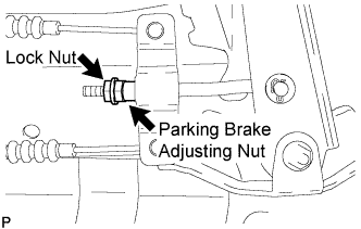
Depress the parking brake handle. Hold the parking brake adjusting nut using a wrench, and loosen the lock nut.
-
Turn the parking brake adjusting nut until the parking brake handle travel meets the above specification.
Parking brake control handle travel 10 to 16 clicks at 200 N (20 kgf, 44 lbf) -
Count the number of clicks after depressing and releasing the parking brake control handle 3 or 4 times.
-
Check whether the parking brake drags or not.
-
When operating the parking brake control handle, check that the parking brake indicator light comes on.
Standard Brake warning light always comes on at the first click. -
Hold the parking brake adjusting nut using a wrench, and tighten the lock nut.
- Torque:
- 14.5 N*m { 148 kgf*cm, 11 ft.*lbf }
-
Lower the vehicle.
-
-
ABS SPEED SENSOR SIGNAL