PROPELLER SHAFT ASSEMBLY (for Long Wheelbase) REMOVAL

-
REMOVE PROPELLER SHAFT ASSEMBLY
-
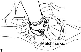
Put matchmarks on both flanges.
-
Remove the 4 nuts, bolts and washers.
Tech Tips
If the flange connection is hard to separate, temporarily tighten one nut only and evenly tap the flange with a brass bar and hammer to separate the propeller shaft assembly from the differential companion flange.
-
Remove the propeller shaft assembly.
-
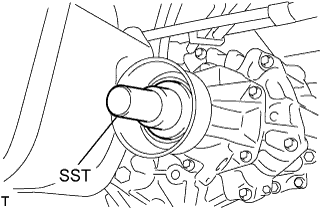
Insert SST in the transmission to prevent oil leakage.
Note
Do not damage the oil seal.
-
Use the following SST for the automatic transmission
- SST
- 09325-40010
-
Use the following SST for the manual transmission
- SST
- 09325-20010
-
-
-
INSPECT PROPELLER SHAFT ASSEMBLY
-
Visually check the propeller shaft assembly.
-
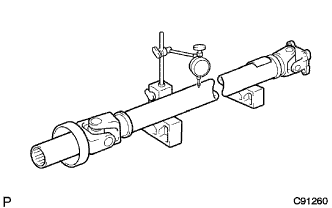
Using a dial indicator, inspect the runout of the shaft tube.
Runout of propeller shaft Shaft tube length mm (in.) Maximum runout mm (in.) 800 (31.496) or more 0.4 (0.0157) Less than 800 (31.496) 0.3 (0.0118)
-
-
INSPECT UNIVERSAL JOINT SPIDER ASSEMBLY
-
Check that the spider bearing rotates smoothly.
-
Check that there is no play in the spider bearing.
-
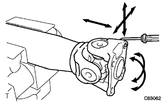
Using a spring tension gauge, hang the hook of the spring tension gauge on the bolt hole of the flange yoke and measure the rotating force.
Maximum 1.1 N*m (11.2 kgf*cm, 9.68 in.*lbf) Note
Measurement of rotating force should be done at 2 positions for each universal joint by 90° in opposite directions (flange yoke side and end yoke side). When the rotating force is less than the standard, use a thicker retainer ring. When it exceeds the standard, use a thinner one.
-