OUTPUT SHAFT DISASSEMBLY

-
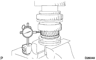
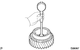
INSPECT 1ST GEAR THRUST CLEARANCE
-
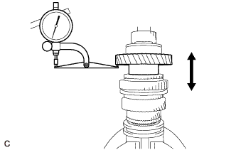
Using a dial indicator, measure the thrust clearance of the 1st gear.
Standard clearance 0.20 to 0.45 mm (0.0079 to 0.0177 in.)
-
-
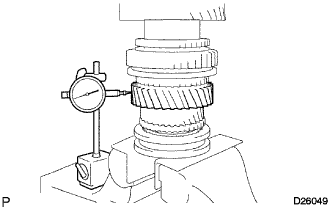
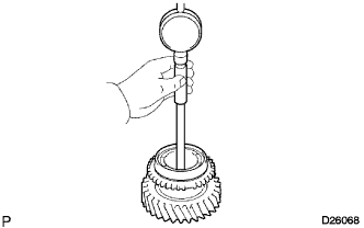
INSPECT 2ND GEAR THRUST CLEARANCE
-
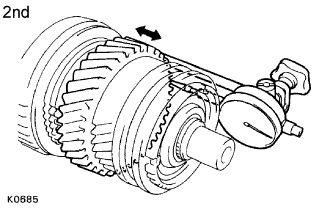
Using a dial indicator, measure the thrust clearance of the 2nd gear.
Standard clearance 0.10 to 0.25 mm (0.0039 to 0.0098 in.)
-
-
INSPECT 3RD GEAR THRUST CLEARANCE
-
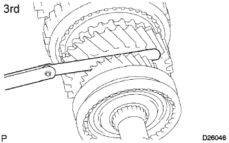
Using a feeler gauge, measure the thrust clearance of the 3rd gear.
Standard clearance 0.10 to 0.25 mm (0.0039 to 0.0098 in.)
-
-
INSPECT 1ST GEAR RADIAL CLEARANCE
-
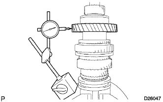
Using a dial indicator, measure the radial clearance of the 1st gear.
Standard clearance 0.020 to 0.073 mm (0.0008 to 0.0029 in.) If the clearance is not within the specified values, replace the 1st gear needle roller bearing with a new one.
-
-
INSPECT 2ND GEAR RADIAL CLEARANCE
-
Using a dial indicator, measure the radial clearance of the 2nd gear.
Standard clearance 0.015 to 0.068mm (0.0006 to 0.0027 in.) If the clearance is not within the specified values, replace the 2nd gear needle roller bearing with a new one.
-
-
INSPECT 3RD GEAR RADIAL CLEARANCE
-
Using a dial indicator, measure the radial clearance of the 3rd gear.
Standard clearance 0.015 to 0.068 mm (0.0006 to 0.0027 in.) If the clearance is not within the specified values, replace the 3rd gear needle roller bearing with a new one.
-
-
REMOVE 1ST GEAR
-
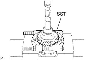
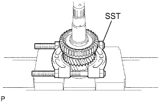
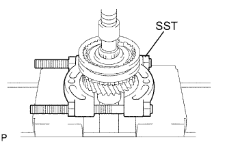
Using SST and a press, remove the 5th gear, output shaft center bearing, 1st gear thrust washer and 1st gear from the output shaft.
- SST
- 09950-00020
-
-
REMOVE SYNCHRONIZER RING NO.1 (for 1st Gear (2TR-FE))
-
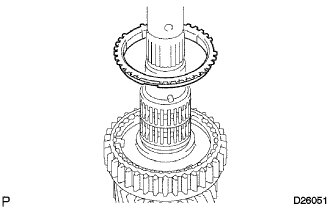
Remove the synchronizer ring No.1 from the output shaft.
-
-
REMOVE SYNCHRONIZER RING SET NO.1 (for 1st Gear (2KD-FTV))
-
Remove the synchronizer ring set No.1 from the output shaft.
-
-
REMOVE 1ST GEAR THRUST WASHER PIN
-
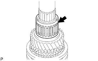
Remove the 1st gear thrust washer pin from the output shaft.
-
-
REMOVE 1ST GEAR NEEDLE ROLLER BEARING
-
Remove the 1st gear needle roller bearing from the output shaft.
-
-
REMOVE 1ST GEAR BEARING SPACER
-
Remove the 1st gear bearing spacer from the output shaft.
-
-
REMOVE BEARING SHAFT SNAP RING
-
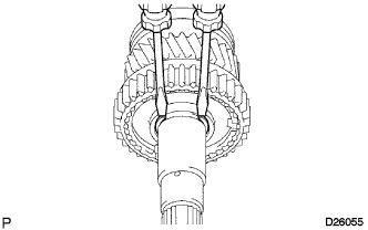
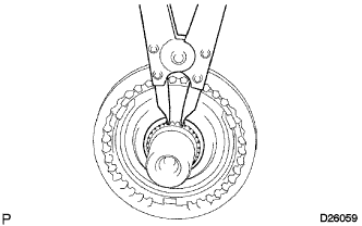
Using 2 screwdrivers and a hammer, remove the bearing shaft snap ring from the output shaft.
Note
Use a shop rag to prevent the snap ring from flying off.
-
-
REMOVE 2ND GEAR
-
Using SST and a press, remove the transmission clutch hub No.1, reverse gear, synchronizer ring No.1 and 2nd gear from the output shaft.
- SST
- 09950-00020
-
-
REMOVE 2ND GEAR NEEDLE ROLLER BEARING
-
Remove the 2nd gear needle roller bearing from the output shaft.
-
-
REMOVE REVERSE GEAR
-
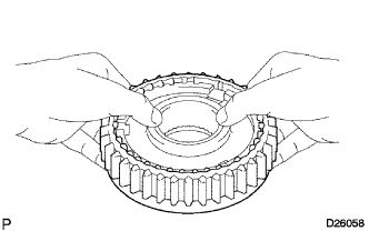
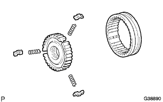
Remove the reverse gear, 3 synchromesh shifting keys No.1 and 3 synchromesh shifting key springs.
Use a shop rag to prevent the shifting keys and the shifting key springs from popping out.
-
-
REMOVE CLUTCH HUB SET SHAFT SNAP RING
-
Using snap ring pliers, remove the clutch hub set shaft snap ring from the output shaft.
Note
Do not damage the sliding surface of the bearing.
-
-
REMOVE 3RD GEAR
-
Using SST and a press, remove the clutch hub No.2 with the hub sleeve No.2, synchronizer ring No.2 and 3rd gear from the output shaft.
- SST
- 09950-00020
-
-
REMOVE 3RD GEAR NEEDLE ROLLER BEARING
-
Remove the 3rd gear needle roller bearing from the output shaft.
-
-
REMOVE TRANSMISSION HUB SLEEVE NO.2
-
Remove the transmission hub sleeve No.2, 3 synchromesh shifting key springs and 3 synchromesh shifting keys No.2 from the transmission clutch hub No.2.
-
-
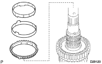
INSPECT OUTPUT SHAFT
-
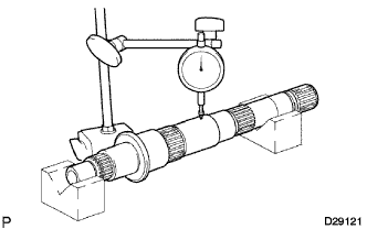
Using a dial indicator, measure the runout of the output shaft.
Maximum runout 0.03 mm (0.0012 in.) If the runout is greater than the maximum, replace the output shaft with a new one.
-
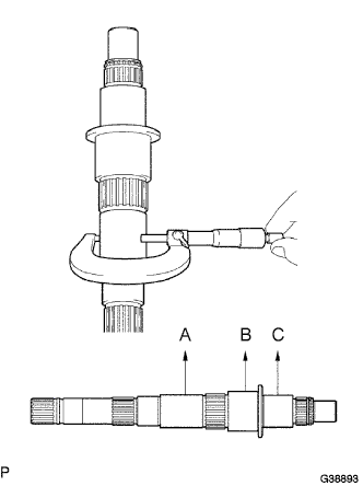
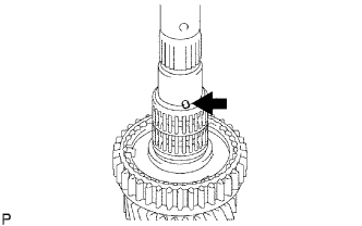
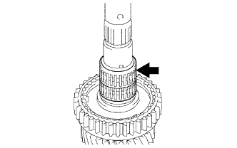
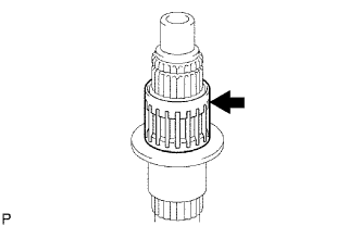
Using a micrometer, measure the outer diameter of the output shaft at points A, B and C.
Standard diameter 38.979 to 38.995 mm (1.5334 to 1.5352 in.) for A 46.984 to 47.000 mm (1.8498 to 1.8504 in.) for B 37.984 to 38.000 mm (1.4954 to 1.4961 in.) for C Minimum diameter 38.979 mm (1.5334 in.) for A 46.984 mm (1.8498 in.) for B 37.984 mm (1.4954 in.) for C If the outer diameter is less than the minimum, replace the output shaft with a new one.
-
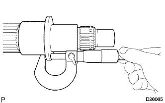
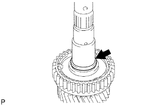
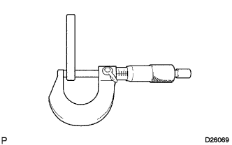
Using a micrometer, measure the thickness of the output shaft flange as shown in the illustration.
Standard thickness 4.8 to 5.2 mm (0.1890 to 0.2047 in.) If the thickness is not within the specified values, replace the output shaft.
-
-
INSPECT 3RD GEAR
-
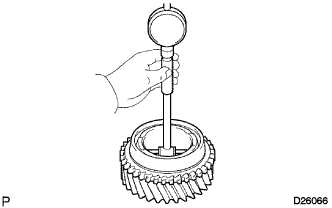
Using a cylinder gauge, measure the inner diameter of the 3rd gear.
Standard diameter 44.015 to 44.040 mm (1.7329 to 1.7339 in.) Maximum diameter 44.040 mm (1.7339 in.) If the inner diameter is greater than the maximum, replace the 3rd gear with a new one.
-
-
INSPECT 2ND GEAR
-
Using a cylinder gauge, measure the inner diameter of the 2nd gear.
Standard diameter 53.015 to 53.040 mm (2.0872 to 2.0881 in.) Maximum diameter 53.040 mm (2.0881 in.) If the inner diameter is greater than the maximum, replace the 2nd gear with a new one.
-
-
INSPECT 1ST GEAR
-
Using a cylinder gauge, measure the inner diameter of the 1st gear.
Standard diameter 46.015 to 46.040 mm (1.812 to 1.813 in.) Maximum diameter 46.040 mm (1.8126 in.) If the inner diameter is greater than the maximum, replace the 1st gear with a new one.
-
-
INSPECT 1ST GEAR THRUST WASHER
-
Using a micrometer, measure the thickness of the 1st gear thrust washer.
Standard thickness 5.95 to 6.05 mm (0.2346 to 0.2382 in.) Minimum thickness 5.96 mm (0.2346 in.) If the thickness is less than the minimum, replace the 1st gear thrust washer.
-
-
INSPECT SYNCHRONIZER RING SET NO.1 (for 1st Gear (2KD-FTV))
-
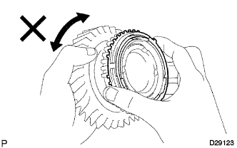
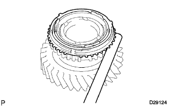
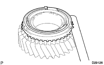
Apply gear oil to the cone of the 1st gear, and check that it does not turn in either direction while pushing the synchronizer ring set No.1 (for the first synchronizer ring).
If it turns, replace the synchronizer ring set No.1.
-
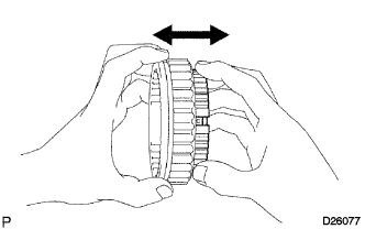
Measure the clearance between the synchronizer ring No.1 and 1st gear while pushing the synchronizer ring No.1 against the cone of the 1st gear.
Standard clearance 0.65 to 1.75 mm (0.0256 to 0.0689 in.) If the clearance is not within the specified values, replace the synchronizer ring No.1 with a new one.
-
-
INSPECT SYNCHRONIZER RING NO.1 (for 1st Gear (2TR-FE))
-
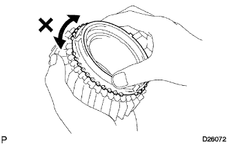
Apply gear oil to the cone of the 1st gear, and check that it does not turn in either direction while pushing the synchronizer ring No.1 (for the first synchronizer ring).
If it turns, replace the synchronizer ring No.1.
-
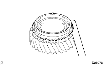
Measure the clearance between the synchronizer ring No.1 and 1st gear while pushing the synchronizer ring No.1 against the cone of the 1st gear.
Standard clearance 0.75 to 1.65 mm (0.0295 to 0.0649 in.) If the clearance is not within the specified values, replace the synchronizer ring No.1 with a new one.
-
-
INSPECT SYNCHRONIZER RING SET NO.1 (for 2nd Gear)
-
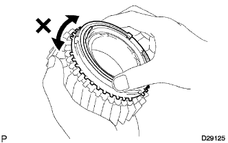
Apply gear oil to the cone of the 2nd gear, and check that it does not turn in either direction while pushing the synchronizer ring set No.1 (for the second synchronizer ring).
If it turns, replace the synchronizer ring set No.1.
-
Measure the clearance between the synchronizer ring set No.1 (for the second synchronizer ring) and 2nd gear while pushing the synchronizer ring set No.1 against the cone of the 2nd gear.
Standard clearance 0.65 to 1.75 mm (0.0256 to 0.0689 in.) If the clearance is not within the specified values, replace the synchronizer ring set No.1 (for the second synchronizer ring) with a new one.
-
-
INSPECT SYNCHRONIZER RING NO.2 (for 3rd Gear)
-
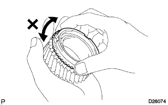
Apply gear oil to the cone of the 3rd gear, and check that it does not turn in either direction while pushing the synchronizer ring No.2 (for the third synchronizer ring).
If it turns, replace the synchronizer ring No.2.
-

Measure the clearance between the synchronizer ring No.2 (for the third synchronizer ring) and 3rd gear while pushing the synchronizer ring No.2 (for the second synchronizer ring) against the cone of the 3rd gear.
Standard clearance 0.75 to 1.65 mm (0.0295 to 0.0650 in.) If the clearance is not within the specified values, replace the synchronizer ring No.2 (for the third synchronizer ring) with a new one.
-
-
INSPECT REVERSE GEAR
-
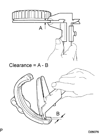
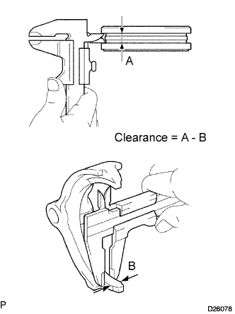
Using vernier calipers, measure the width of the reverse gear groove and the thickness of the claw part on the gear shift fork No.1, and calculate the clearance.
Standard clearance (A - B) 0.15 to 0.41 mm (0.0060 to 0.0161 in.) If the clearance is not within the specified values, replace the reverse gear and the shift fork No.1 with new ones.
-
-
INSPECT TRANSMISSION CLUTCH HUB NO.1
-
Check that the transmission clutch hub No.1 and reverse gear slide smoothly each other.
-
Check the tip of the spline gear sleeve of the reverse gear for wear.
If there are any defects, replace the transmission clutch hub No.1.
-
-
INSPECT TRANSMISSION HUB SLEEVE NO.2
-
Using vernier calipers, measure the width of the transmission hub No.2 groove and the thickness of the claw of the gear shift fork No.2.
Standard clearance (A - B) 0.15 to 0.35 mm (0.0059 to 0.0138 in.) If the clearance is not within the specified values, replace the transmission hub sleeve No.2 and the shift fork No.2 with new ones.
-
-
INSPECT TRANSMISSION CLUTCH HUB NO.2
-
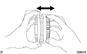
Check the sliding condition between the transmission clutch hub No.2 and the transmission hub sleeve No.2.
-
Check the tip of the spline gear sleeve of the reverse gear for wear.
-