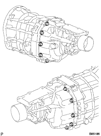
MANUAL TRANSMISSION UNIT DISASSEMBLY

-
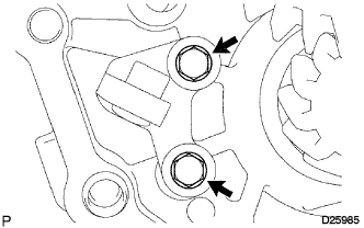
REMOVE MANUAL TRANSMISSION FILLER PLUG
-
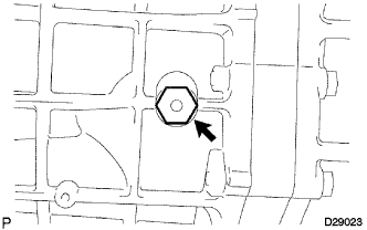
Remove the filler plug and gasket from the transmission case.
-
-
REMOVE DRAIN (MTM) PLUG SUB-ASSEMBLY
-
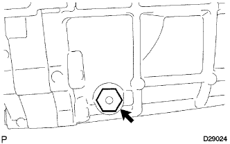
Remove the drain plug and gasket from the transmission case.
-
-
REMOVE CLUTCH HOUSING
-
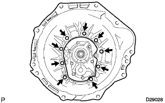
Remove the 9 bolts.
-
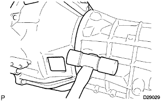
Using a plastic hammer, remove the clutch housing from the transmission case.
-
-
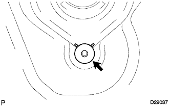
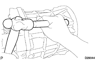
REMOVE BACK UP LIGHT SWITCH ASSEMBLY
-
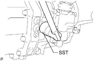
Using SST, remove the back up light switch and gasket from the transmission case.
-
-
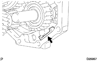
REMOVE SPEEDOMETER SENSOR
-
Remove the bolt and speedometer sensor from the extension housing.
-
Remove the O-ring from the speedometer sensor.
-
-
REMOVE EXTENSION HOUSING(MTM) COVER
-
Remove the 6 bolts, extension housing (MTM) cover and gasket.
-
-
REMOVE EXTENSION HOUSING DUST(MTM) DEFLECTOR
-
Using a brass bar and a hammer, remove the extension housing dust deflector from the extension housing.
-
-
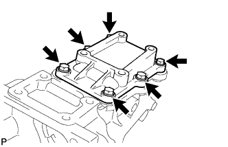
REMOVE SHIFT LEVER SHAFT HOUSING SUB-ASSEMBLY
-
Remove the 6 bolts.
-
Using a plastic hammer, remove the shift lever shaft housing sub-assembly.
-
-
REMOVE EXTENSION (MTM) HOUSING SUB-ASSEMBLY
-
Remove the 10 bolts.
-
Using a plastic hammer, remove the extension housing.
-
-
REMOVE EXTENSION HOUSING OIL RECEIVER PIPE
-
Remove the bolt and oil receiver pipe from the extension housing.
-
-
REMOVE EXTENSION HOUSING OIL RECEIVER PIPE NO.1
-
Remove the extension housing oil receiver pipe No.1.
-
-
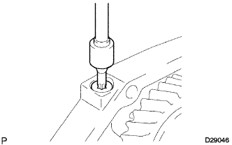
REMOVE MANUAL TRANSMISSION EXTENSION HOUSING OIL SEAL
-
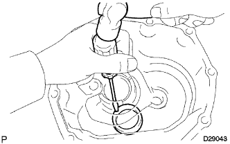
Using a screwdriver and hammer, remove the extension housing oil seal from the extension housing.
-
-
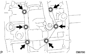
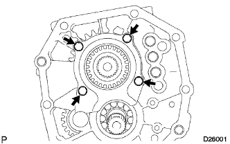
REMOVE BEARING RETAINER FRONT(MTM)
-
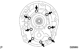
Remove the 8 bolts.
-
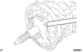
Using a brass bar and hammer, remove the retainer from the transmission case.
-
-
REMOVE TRANSMISSION FRONT BEARING RETAINER OIL SEAL
-
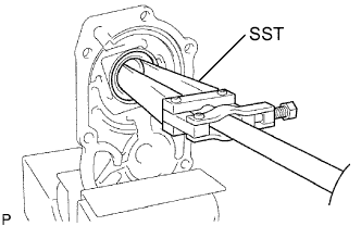
Fix the front bearing retainer in a vise in aluminum plate.
-
Using SST, remove the transmission front bearing retainer oil seal.
- SST
- 09308-00010
-
-
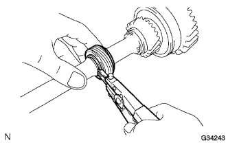
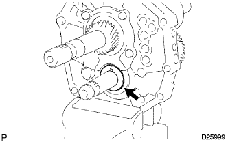
REMOVE FRONT BEARING SHAFT SNAP RING
-
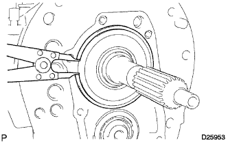
Using a snap ring expander, remove the front bearing shaft snap ring from the transmission case.
-
-
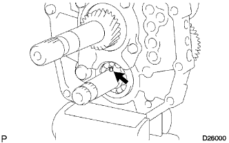
REMOVE COUNTER GEAR FRONT BEARING SNAP RING NO.1
-
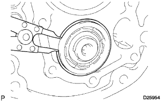
Using a snap ring expander, remove the counter gear front bearing snap ring No.1 from the transmission case.
-
-
REMOVE MANUAL TRANSMISSION CASE
-
Using a brass bar and hammer, remove the transmission case from the intermediate plate.
-
-
REMOVE TRANSMISSION MAGNET
-
Remove the transmission magnet from the intermediate plate.
-
-
FIX INTERMEDIATE PLATE
-
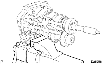
Fix the intermediate plate in a vise in between aluminum plates.
-
-
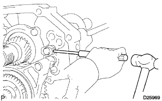
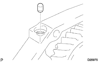
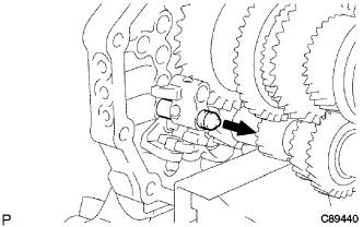
REMOVE SHIFT DETENT BALL SPRING SEAT NO.1
-
Using a "torx" socket wrench T40, remove the shift detent ball spring seat No.1 from the intermediate plate.
-
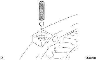
Using a magnet hand, remove the compression spring and the shift detent ball from the intermediate plate.
-
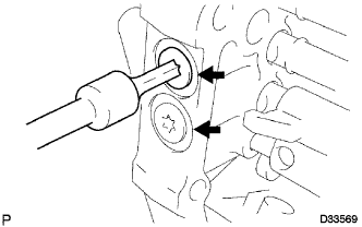
Using a "torx" socket wrench T40, remove the 2 shift detent ball spring seats No.1 from the intermediate plate.
-
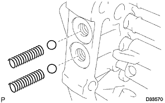
Using a magnet hand, remove the 2 compression springs and the 2 shift detent balls from the intermediate plate.
-
-
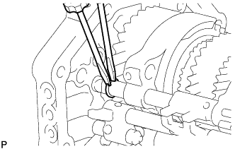
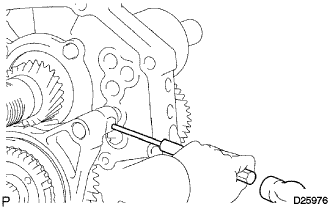
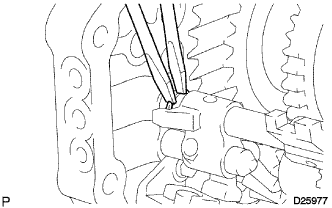
REMOVE SHIFT FORK SHAFT STOPPER
-
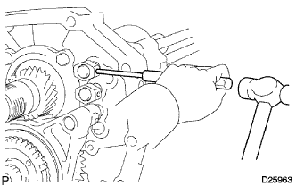
Using a pin punch (5 mm) and hammer, remove the slotted spring pin from the gear shift fork shaft No.1.
-
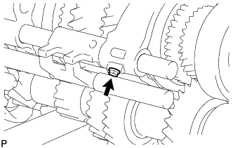
Remove the shift fork shaft stopper from the gear shift fork shaft No.1.
-
-
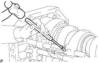
REMOVE GEAR SHIFT FORK SHAFT NO.1
-
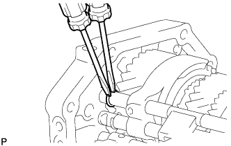
Using 2 screwdrivers and a hammer, remove the snap ring from the gear shift fork shaft No.1.
Note
Use a shop rag to prevent the snap ring from flying off.
-
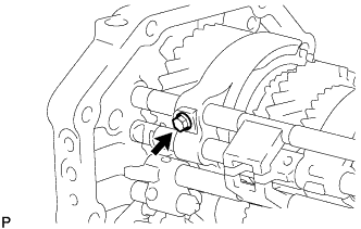
Remove the shift fork set bolt from the gear shift fork No.1.
-
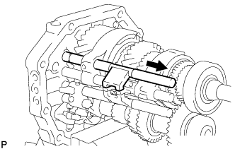
Remove the gear shift fork shaft No.1 from the intermediate plate.
-
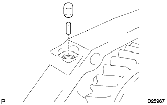
Using a magnet hand, remove the shift interlock No.1 roller and the shift interlock pin (ball) from the intermediate plate.
-
-
REMOVE SHIFT FORK SHAFT STOPPER
-
Using a pin punch (5 mm) and a hammer, remove the slotted spring pin from the gear shift fork shaft No.2.
-
Remove the shift fork shaft stopper from the gear shift fork shaft No.2.
-
-
REMOVE GEAR SHIFT FORK SHAFT NO.2
-
Using 2 screwdrivers and a hammer, remove the snap ring from the gear shift fork shaft No.2.
Note
Use a shop rag to prevent the snap ring from flying off.
-
Remove the shift fork set bolt from the gear shift fork No.2.
-
Using a pin punch (5 mm) and hammer, remove the slotted spring pin from the gear shift fork shaft No.2.
-
Remove the gear shift fork shaft No.2 and gear shift head No.2.
-
Remove the gear shift fork No.1 and gear shift fork No.2 from the output shaft.
-
Using a magnet hand, remove the shift interlock No.1 roller from the intermediate plate.
-
-
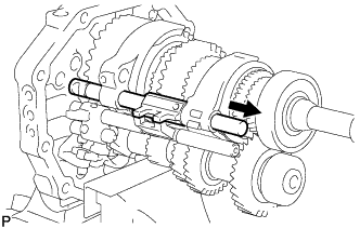
REMOVE REVERSE SHIFT FORK SHAFT
-
Using a pin punch (5 mm) and hammer, remove the slotted spring pin from the reverse shift fork shaft.
-
Using 2 screwdrivers and a hammer, remove the snap ring from the reverse shift fork shaft.
Note
Use a shop rag to prevent the snap ring from flying off.
-
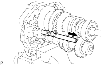
Remove the reverse shift fork shaft and gear shift fork No.3.
-
Using a magnet hand, remove the shift interlock No.1 roller from the intermediate plate.
-
Using a magnet hand, remove the reverse shift fork ball from the reverse shift fork.
-
-
REMOVE GEAR SHIFT FORK SHAFT NO.4
-
Using 2 screwdrivers and a hammer, remove the shift fork shaft snap ring from the gear shift fork shaft No.4.
Note
Use a shop rag to prevent the snap ring from flying off.
-
Remove the shift fork shaft No.4 from the intermediate plate.
Note
Cover the hole with a shop rag to prevent the reverse shift fork ball from popping out.
-
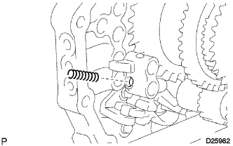
Using a magnet hand, remove the compression spring from the reverse shift fork.
-
-
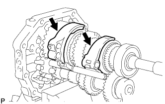
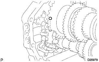
REMOVE REVERSE SHIFT FORK
-
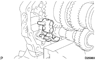
Remove the reverse shift fork together with the reverse shift arm from the intermediate plate.
-
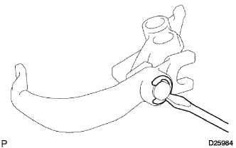
Using a screwdriver, remove the reverse shift arm end shaft ring and the reverse shift fork from the reverse shift arm.
-
-
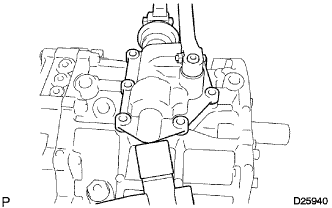
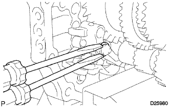
REMOVE REVERSE SHIFT ARM BRACKET
-
Remove the 2 bolts and reverse shift arm bracket from the intermediate plate.
-
-
REMOVE SPEEDOMETER DRIVE (MTM) GEAR
-
Using snap ring expander, remove the snap ring.
-
Remove the speedometer drive gear and ball.
-
Using a magnet hand, remove the steel ball.
-
Using snap ring expander, remove the snap ring.
-
-
REMOVE OUTPUT SHAFT BEARING SHAFT SNAP RING
-
Using 2 screwdrivers and a hammer, remove the output shaft bearing shaft snap ring from the output shaft.
-
-
REMOVE OUTPUT SHAFT REAR BEARING
-
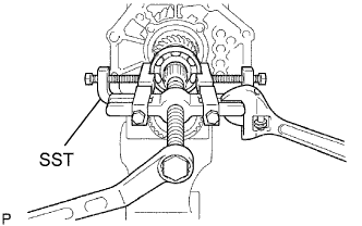
Using SST, remove the output shaft rear bearing and output shaft spacer from the output shaft.
- SST
- 09950-40011 ( 09951-04010, 09952-04010, 09953-04020, 09954-04010, 09955-04051, 09957-04010, 09958-04011 )
-
-
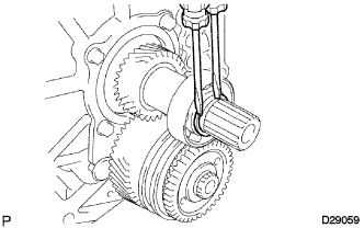
INSPECT COUNTER SHAFT 5TH GEAR THRUST CLEARANCE
-
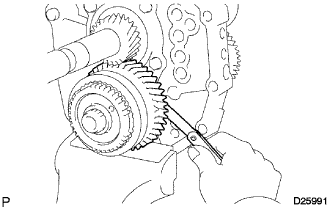
Using a feeler gauge, measure the counter shaft 5th gear thrust clearance.
Standard clearance 0.10 to 0.35 mm (0.0039 to 0.0138 in.)
-
-
INSPECT COUNTER SHAFT 5TH GEAR RADIAL CLEARANCE
-
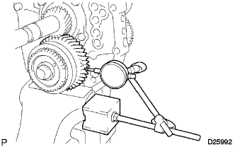
Using a dial indicator, measure the radial clearance of the counter shaft 5th gear.
Standard clearance 0.015 to 0.068 mm (0.0059 to 0.0027 in.) If the clearance is not within the specified values, replace the counter 5th gear bearing with a new one.
-
-
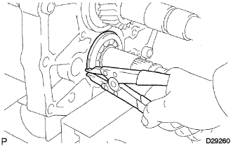
REMOVE COUNTER GEAR REAR SHAFT SNAP RING
-
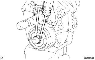
Using 2 screwdrivers and a hammer, remove the counter gear rear shaft snap ring from the counter gear.
-
-
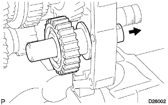
REMOVE TRANSMISSION HUB SLEEVE NO.3
-
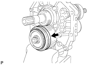
Remove the No. 3 transmission hub sleeve from the counter 5th gear.
-
-
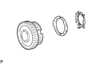
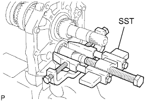
REMOVE COUNTER SHAFT 5TH GEAR
-
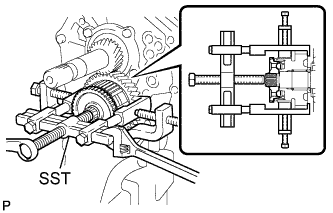
Using SST, remove the counter 5th gear together with the 2 No. 3 synchromesh shifting keys, 2 No. 3 synchromesh shifting key springs, No. 3 synchronizer ring and No. 5 gear spline piece from the counter gear.
- SST
- 09950-40011 ( 09951-04020, 09952-04010, 09953-04020, 09954-04010, 09955-04021, 09957-04010, 09958-04011 )
-
-
REMOVE GEAR SPLINE PIECE NO.5
-
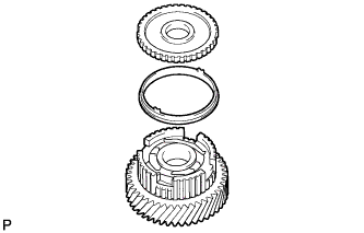
Remove the No. 5 gear spline piece from the counter 5th gear.
-
-
REMOVE SYNCHRONIZER RING OUTER NO.3
-
Remove the synchronizer ring from the counter 5th gear.
-
-
REMOVE COUNTER 5TH GEAR BEARING
-
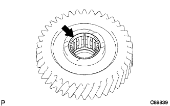
Remove the counter 5th gear bearing from the counter 5th gear.
-
-
REMOVE SYNCHROMESH SHIFTING KEY SPRING NO.3
-
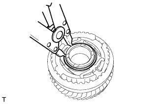
Using a snap ring expander, remove the snap ring.
-
Remove the synchromesh shifting key spring No. 3 and 2 synchromesh shifting keys No. 3 from the counter 5th gear.
-
-
REMOVE 5TH GEAR THRUST WASHER
-
Remove the 5th gear thrust washer from the counter gear.
-
-
REMOVE 5TH GEAR THRUST WASHER PIN
-
Remove the 5th gear thrust washer pin from the counter gear.
-
-
REMOVE OUTPUT SHAFT REAR BEARING(MTM) RETAINER
-
Remove the 4 bolts and output shaft rear bearing retainer from the intermediate plate.
-
-
REMOVE REVERSE IDLER GEAR SUB-ASSEMBLY
-
Pull out the reverse idler gear shaft to the rear side and remove the reverse idler gear from the intermediate plate.
-
-
REMOVE COUNTER SHAFT CENTER BEARING
-
Using a snap ring expander, remove the snap ring.
-
Using SST, remove the counter shaft center bearing from the intermediate plate.
- SST
- 09950-40011 ( 09951-04010, 09952-04010, 09953-04020, 09954-04010, 09955-04011, 09957-04010, 09958-04011 )
Tech Tips
Remove the bearing while tapping the tip of the counter gear so that the counter gear assembly is not pushed forward into the side wall of the output shaft gear.
-
-
REMOVE COUNTER GEAR
-
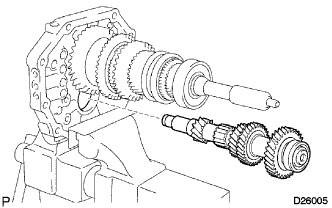
Remove the counter gear assembly from the intermediate plate.
-
-
REMOVE INPUT SHAFT ASSEMBLY
-
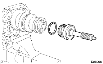
Remove the input shaft assembly and synchronizer ring No.2 from the output shaft.
Note
Do not drop the input shaft bearing and synchronizer ring No.2.
-
-
REMOVE OUTPUT SHAFT BEARING SHAFT SNAP RING
-
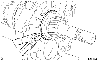
Using a snap ring expander, remove the output shaft bearing shaft snap ring from the output shaft.
-
-
REMOVE OUTPUT SHAFT ASSEMBLY
-
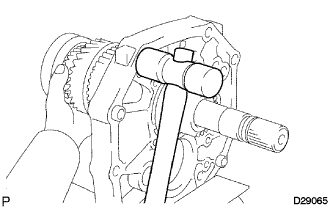
Using a plastic hammer, remove the output shaft assembly by tapping the intermediate plate.
-