MANUAL TRANSMISSION ASSEMBLY (for 1KD-FTV) INSTALLATION

-
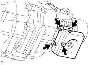
INSTALL REAR ENGINE MOUNTING INSULATOR ASSEMBLY
-
Install the rear engine mounting insulator assembly with the 4 bolts.
- Torque:
- 29 N*m { 296 kgf*cm, 21 ft.*lbf }
-
-
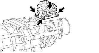
INSTALL EXTENSION HOUSING DYNAMIC DAMPER (WITH DYNAMIC DAMPER)
-
Install the extension housing dynamic damper with the 4 bolts.
- Torque:
- 30 N*m { 306 kgf*cm, 22 ft.*lbf }
-
-
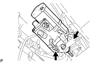
INSTALL MANUAL TRANSMISSION ASSEMBLY
-
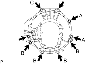
Install the manual transmission assembly with the 9 bolts.
- Torque:
- 72 N*m { 729 kgf*cm, 53 ft.*lbf }
Tech Tips
-
The A bolts in the illustration tighten the control cable bracket together.
-
The B bolts in the illustration tighten the stiffener plate together.
-
Bolt C in the illustration tightens the harness clamp bracket together.
-
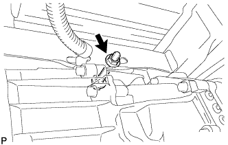
Install the transmission assembly to the frame with the bolt, nut, and 2 washers.
- Torque:
- 98 N*m { 999 kgf*cm, 72 ft.*lbf }
Note
-
Insert the bolt from the left side of the vehicle.
-
Tighten the nut while holding the bolt.
-
-
INSTALL STARTER ASSEMBLY (for 2.2 kW Type)
-
Install the starter with the bolt and nut.
- Torque:
- 68 N*m { 693 kgf*cm, 50 ft.*lbf }
-
Connect the wire harness to terminal 30 with the nut.
- Torque:
- 9.8 N*m { 100 kgf*cm, 7.2 ft.*lbf }
-
Close the terminal cap.
-
Connect the terminal 50 connector to the starter.
-
for Wide Body:
Install the ground cable with the bolt.
- Torque:
- 25 N*m { 250 kgf*cm, 18 ft.*lbf }
-
-
INSTALL STARTER ASSEMBLY (for 2.7 kW Type)
-
for Automatic Transmission:
Install the starter with the bolt and 2 nuts.
- Torque:
- 68 N*m { 693 kgf*cm, 50 ft.*lbf }
-
for Manual Transmission:
Install the starter with the bolt and nut.
- Torque:
- 68 N*m { 693 kgf*cm, 50 ft.*lbf }
-
Connect the wire harness to terminal 30 with the nut.
- Torque:
- 21 N*m { 214 kgf*cm, 15 ft.*lbf }
-
Close the terminal cap.
-
Connect the terminal 50 connector to the starter.
-
for Wide Body:
Install the wire ground cable with the bolt.
- Torque:
- 25 N*m { 250 kgf*cm, 18 ft.*lbf }
-
-
INSTALL CLUTCH RELEASE CYLINDER ASSEMBLY
-
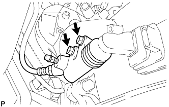
Install the clutch release cylinder with the 2 bolts.
- Torque:
- 12 N*m { 119 kgf*cm, 8.6 ft.*lbf }
-
-
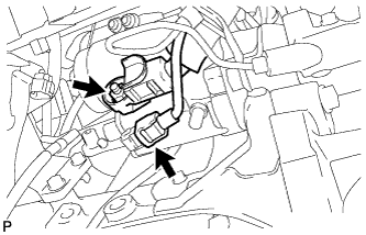
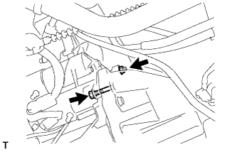
INSTALL WIRE HARNESS
-
Connect the speed sensor connector.
-
Connect the back-up light switch connector.
-
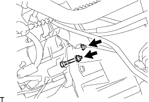
Install the ground cable with the bolt.
- Torque:
- 13 N*m { 130 kgf*cm, 10 ft.*lbf }
-
-
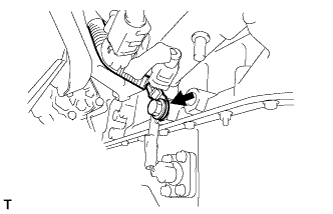
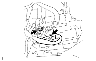
CONNECT TRANSMISSION CONTROL CABLE ASSEMBLY
-
Install 2 new clips to the No. 1 transmission control cable bracket.
-
Connect the transmission control cable assembly to the No. 1 transmission control cable bracket.
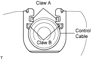
Note
-
Make sure that A claws of the clips are firmly installed into the bracket grooves.
-
Make sure that the cable is set in the clip with both B claws erected to prevent slippage of the cable in the opposite direction.
-
-
Align the matchmarks on the control cable assemblies and the outer levers.
-
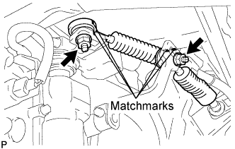
Install the transmission control cable assembly to the outer levers with the 2 nuts.
- Torque:
- 37 N*m { 377 kgf*cm, 27 ft.*lbf }
-
-
INSTALL PROPELLER SHAFT ASSEMBLY (for Long Wheelbase)
-
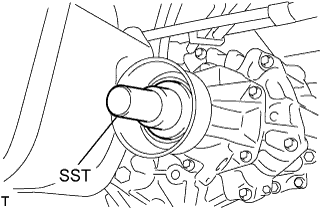
Remove the SST from the extension housing.
-
Install the propeller shaft assembly in the extension housing.
-
Align the matchmarks on the propeller shaft flange and differential flange.
-
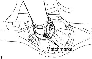
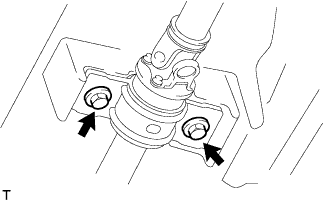
Install the propeller shaft assembly with the 4 nuts, 4 bolts and 4 washers.
- Torque:
- 74 N*m { 755 kgf*cm, 54 ft.*lbf }
-
-
INSTALL PROPELLER WITH CENTER BEARING SHAFT ASSEMBLY (for Super Long Wheelbase)
-
Remove the SST from the extension housing.
-
Install the propeller with center bearing shaft assembly in the extension housing.
-
Install the center support bearing assembly No.1, and temporarily tighten the 2 bolts.
-
Align the matchmarks on the propeller shaft flange and differential flange.
-
Install the propeller shaft assembly with the 4 nuts, 4 bolts and 4 washers.
- Torque:
- 74 N*m { 755 kgf*cm, 54 ft.*lbf }
-
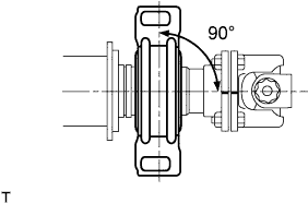
Check that the center line of the bracket is at right angles to the shaft axial direction.
-
Adjust the center support bearing assembly No.1.
Tech Tips
-
With the vehicle unladen, adjust the center support bearing No.1 to maintain the angles, as shown.
-
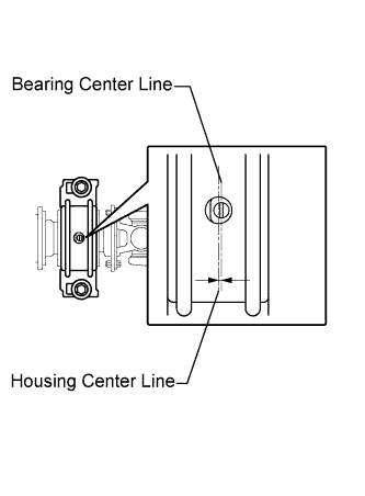
In the same conditions, check the center line in the axial direction. Adjust the bearing if necessary.
-
The center bearing center line and center bearing housing center line must be adjusted to within -1.0 to 1.0 mm (-0.0394 to 0.0394 in.) of each other in the vehicle's longitudinal direction with the vehicle unladen.
-
-
Tighten the 2 bolts.
- Torque:
- 36 N*m { 369 kgf*cm, 27 ft.*lbf }
-
-
INSTALL FRONT EXHAUST PIPE ASSEMBLY (for Long Wheelbase)
-
Inspect the compression spring.
-
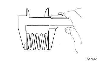
Using vernier calipers, measure the free length of the compression springs.
Minimum length 40.5mm (1.594 in.) Tech Tips
If the free length is less than the minimum, replace the compression spring.
-
-
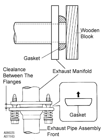
Install the gasket.
-
Fully insert a new gasket to the exhaust manifold by hand.
-
Using a wooden block, uniformly strike the gasket so that the gasket and exhaust manifold are properly fit.
Note
-
Be careful with the installation direction of the gasket.
-
Do not reuse the gasket.
-
Do not damage the gasket.
-
To ensure a proper seal, do not use the exhaust pipe assembly front to force the gasket onto the front exhaust manifold.
-
-
-
Connect the exhaust pipe support, and install the exhaust pipe assembly front with the 4 bolts, 2 compression springs and 2 nuts.
- Torque:
- exhaust manifold side
- 43 N*m { 438 kgf*cm, 32 ft.*lbf }
- exhaust pipe assembly front side
- 48 N*m { 489 kgf*cm, 35 ft.*lbf }
Note
After installation, check that the clearance is almost same at any point between the flanges of the exhaust manifold and exhaust pipe assembly front.
-
-
INSTALL FRONT EXHAUST PIPE ASSEMBLY (for Super Long Wheelbase)
-
Inspect the compression spring.
-
Using vernier calipers, measure the free length of the compression springs.
Minimum length 40.5mm(1.594 in.) Tech Tips
If the free length is less than the minimum, replace the compression spring.
-
-
Install the gasket.
-
Fully insert a new gasket to the exhaust manifold by hand.
-
Using a wooden block, uniformly strike the gasket so that the gasket and exhaust manifold are properly fit.
Note
-
Be careful with the installation direction of the gasket.
-
Do not reuse the gasket.
-
Do not damage the gasket.
-
To ensure a proper seal, do not use the exhaust pipe assembly front to force the gasket onto the front exhaust manifold.
-
-
-
Connect the exhaust pipe support, and install the exhaust pipe assembly front and a new gasket with the 4 bolts, 2 compression springs and 2nuts.
- Torque:
- Exhaust manifold side
- 43 N*m { 438 kgf*cm, 32 ft.*lbf }
- Exhaust pipe assembly center side
- 48 N*m { 489 kgf*cm, 35 ft.*lbf }
Note
After installation, check that the clearance is almost same at any point between the flanges of the exhaust manifold and exhaust pipe assembly front .
-
-
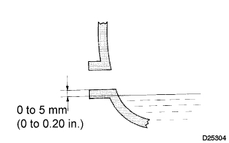
ADD MANUAL TRANSMISSION OIL
-
Park the vehicle in a level place.
-
Remove the transmission filler plug and gasket.
-
Check that the oil surface is within 5 mm (0.20 in.) below the lowest point of the transmission filler plug opening.
Oil grade GL-4 Viscosity SAE 75W-90 Capacity 2.6 liters (2.7 US qts, 2.3 lmp.qts) Note
-
Problems may occur when the oil level is too high or too low.
-
After replacing the oil, drive the vehicle and check the oil level again.
-
-
Check for oil leakage if the oil level is low.
-
Install the transmission filler plug and a new gasket.
- Torque:
- 37 N*m { 377 kgf*cm, 27 ft.*lbf }
-
-
CONNECT CABLE TO NEGATIVE BATTERY TERMINAL
- Torque:
- 5.4 N*m { 55 kgf*cm, 47 in.*lbf }
-
INSPECT FOR EXHAUST GAS LEAK
-
INSPECT FOR OIL LEAK
-
PERFORM INITIALIZATION
Some systems need initialization after reconnecting the cable to the negative battery terminal. Click here