MANUAL TRANSMISSION ASSEMBLY (for 1KD-FTV) REMOVAL

-
DISCONNECT CABLE FROM NEGATIVE BATTERY TERMINAL
-
DRAIN MANUAL TRANSMISSION OIL
-
Remove the filler plug and gasket.
-
Remove the drain plug and gasket, and drain the oil.
-
Install the drain plug with a new gasket.
- Torque:
- 37 N*m { 377 kgf*cm, 27 ft.*lbf }
-
-
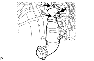
REMOVE FRONT EXHAUST PIPE ASSEMBLY (w/o DPF)
-
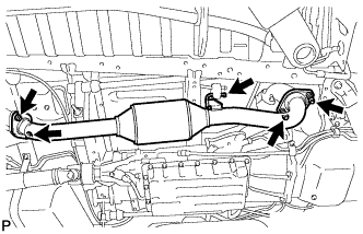
Remove the 2 bolts, 2 nuts and 2 compression springs.
-
Disconnect the No. 4 exhaust pipe support and front exhaust pipe.
-
Remove the 2 gaskets.
-
-
REMOVE FRONT EXHAUST PIPE ASSEMBLY (w/ DPF)
-
REMOVE PROPELLER SHAFT ASSEMBLY (for Long Wheelbase)
-
REMOVE PROPELLER WITH CENTER BEARING SHAFT ASSEMBLY (for Super Long Wheelbase)
-
REMOVE NO. 2 EXHAUST MANIFOLD HEAT INSULATOR (w/ DPF)
-
Remove the 2 bolts and No. 2 exhaust manifold heat insulator.
-
-
REMOVE NO. 3 EXHAUST MANIFOLD HEAT INSULATOR (w/ DPF)
-
Remove the 2 bolts and No. 3 exhaust manifold heat insulator.
-
-
REMOVE CATALYTIC WITH PIPE CONVERTER ASSEMBLY (w/ DPF)
-
Remove the 2 nuts from the catalytic with pipe converter.
-
Remove the 3 nuts, catalytic with pipe converter and gasket.
-
-
REMOVE TURBINE OUTLET ELBOW STAY
-
w/ DPF:
Remove the 2 bolts and turbine outlet elbow stay.
-
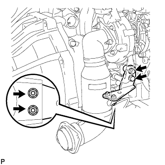
w/o DPF:
Remove the 2 bolts, 2 nuts and turbine outlet elbow stay.
-
-
REMOVE EXHAUST MANIFOLD CONVERTER SUB-ASSEMBLY (w/o DPF)
-
Remove the 3 nuts, exhaust manifold converter and gasket.
-
-
REMOVE TRANSMISSION CONTROL CABLE INSULATOR (for RHD)
-
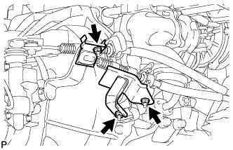
Remove the nut and No. 1 transmission control cable insulator from the select outer lever.
-
Remove the 2 nut and No. 2 transmission control cable insulator from the No. 1 transmission control cable bracket.
-
-
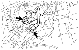
DISCONNECT TRANSMISSION CONTROL CABLE ASSEMBLY
-
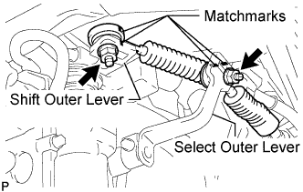
Put matchmarks on the transmission control cable assembly and the select outer lever.
-
Put matchmarks on the transmission control cable assembly and the shift outer lever.
-
Remove the nut and disconnect the transmission control cable assembly from the select outer lever.
-
Remove the nut and disconnect the transmission control cable assembly from the shift outer lever.
-
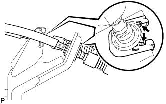
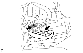
Using a screwdriver, disengage the claws of the 2 clips.
-
Remove the 2 transmission control cable assemblies and 2 clips from the No. 1 transmission control cable bracket.
-
-
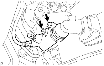
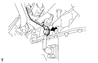
DISCONNECT WIRE HARNESS
-
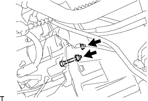
Disconnect the back-up light switch connector.
-
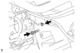
Disconnect the speed sensor connector.
-
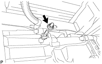
Remove the bolt and separate the ground cable.
-
-
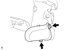
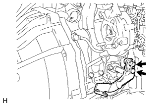
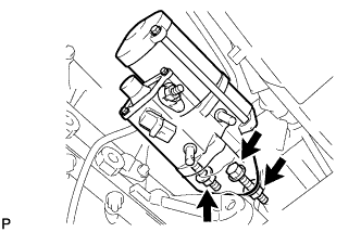
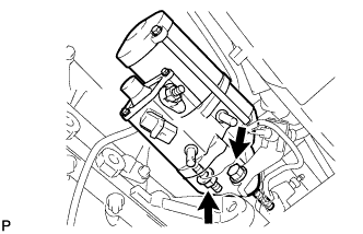
SEPARATE CLUTCH RELEASE CYLINDER ASSEMBLY
-
Remove the 2 bolts and separate the clutch release cylinder assembly.
-
-
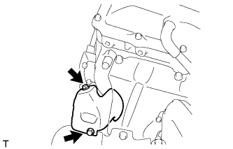
REMOVE STARTER ASSEMBLY (for 2.2 kW Type)
-
for Wide Body:
Remove the bolt and ground cable.
-
Open the terminal cap.
-
Remove the nut and disconnect the wire harness from terminal 30.
-
Disconnect the terminal 50 connector from the starter.
-
for Automatic Transmission:
-
Remove the bolt, 2 nuts and starter.
-
-
for Manual Transmission:
-
Remove the bolt, nut and starter.
-
-
-
REMOVE STARTER ASSEMBLY (for 2.7 kW Type)
-
for Wide Body:
Remove the bolt, then disconnect the ground cable.
-
Open the terminal cap.
-
Remove the nut and disconnect the wire harness from terminal 30.
-
Disconnect the terminal 50 connector from the starter.
-
for Automatic Transmission:
Remove the bolt and 2 nuts, then remove the starter.
-
for Manual Transmission:
Remove the bolt and nut, then remove the starter.
-
-
REMOVE MANUAL TRANSMISSION ASSEMBLY
-
Support the manual transmission assembly with a transmission jack.
-
Remove the bolt, nut, and 2 washers, and then separate the transmission from the frame.
-
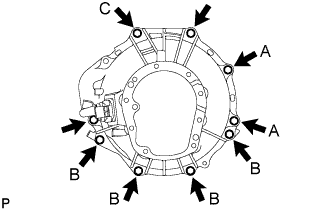
Remove the 9 bolts, manual transmission unit, No. 1 control cable bracket, rear end plate, and cylinder block insulator.
Tech Tips
-
The A bolts in the illustration tighten the control cable bracket together.
-
The B bolts in the illustration tighten the stiffener plate together.
-
Bolt C in the illustration tightens the harness clamp bracket together.
-
-
-
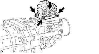
REMOVE EXTENSION HOUSING DYNAMIC DAMPER (WITH DYNAMIC DAMPER)
-
Remove the 4 bolts and extension housing dynamic damper.
-
-
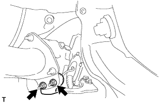
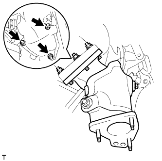
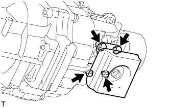
REMOVE REAR ENGINE MOUNTING INSULATOR ASSEMBLY
-
Remove the 4 bolts and rear engine mounting insulator assembly.
-