CLUTCH PEDAL SWITCH INSTALLATION

-
INSTALL CLUTCH SWITCH ASSEMBLY
-
Using a 14 mm union nut wrench, install the clutch switch assembly.
- Torque:
- 16 N*m { 160 kgf*cm, 12 ft.*lbf }
Note
Use the formula to calculate special torque values for situations where a union nut wrench is combined with a torque wrench Click here.
-
Connect the clutch switch connector.
-
-
INSPECT AND ADJUST CLUTCH PEDAL HEIGHT
-
INSTALL NO. 1 AIR DUCT
-
INSTALL LOWER CENTER INSTRUMENT PANEL FINISH PANEL
-
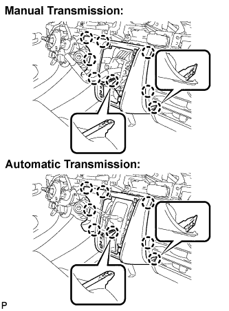
Engage the 8 claws and install the instrument panel finish panel lower center.
-
-
INSTALL SHIFTING HOLE COVER ASSEMBLY
-
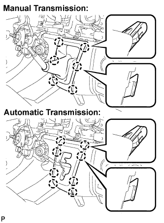
Manual Transmission:
Engage the 6 claws and install the shifting hole cover assembly.
-
Automatic Transmission:
Engage the 8 claws and install the sifting hole cover assembly.
-
-
INSTALL SHIFT LEVER KNOB
-
INSTALL PARKING BRAKE HOLE COVER
-
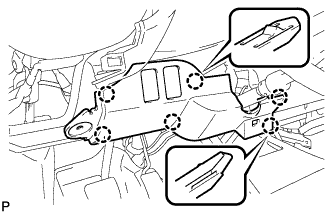
Engage the 6 claws and install the parking brake hole cover.
-
-
INSTALL NO. 1 INSTRUMENT PANEL UNDER COVER SUB-ASSEMBLY
-
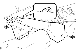
Engage the 3 claws.
-
Install the instrument panel No.1 under cover sub-assembly with the 2 clips.
-
-
INSTALL LOWER INSTRUMENT PANEL FINISH PANEL
-
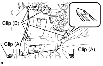
Engage the 4 clips (B).
-
Install the instrument panel finish panel lower with the 2 clips (A).
-
-
CONNECT CABLE TO NEGATIVE BATTERY TERMINAL
- Torque:
- 5.4 N*m { 55 kgf*cm, 47 in.*lbf }
-
PERFORM INITIALIZATION
Some systems need initialization when disconnecting the cable from the negative battery terminal. Click here