CLUTCH UNIT (for 2TR-FE) INSPECTION

-
INSPECT CLUTCH DISC ASSEMBLY
-
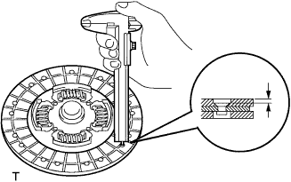
Using vernier calipers, measure the rivet head depth.
Minimum rivet depth 0.3 mm (0.012 in.) If the result is less than the minimum, replace the clutch disc assembly.
-
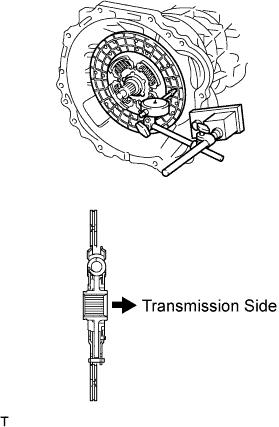
Install the clutch disc assembly to the transmission unit.
Note
Take care not to insert the clutch disc assembly in the wrong direction.
-
Using a dial indicator, check the clutch disc assembly runout.
Maximum runout 0.8 mm (0.031 in.) If the runout exceeds the maximum, replace the clutch disc assembly.
-
-
INSPECT CLUTCH COVER ASSEMBLY
-
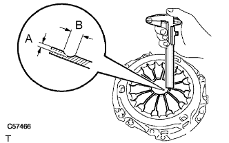
Using vernier calipers, inspect the diaphragm spring for the depth and width of wear.
Maximum A (Depth): B (Width): 0.5 mm (0.020 in.) 6.0 mm (0.236 in.) If the result exceeds the maximum, replace the clutch cover assembly.
-
-
INSPECT FLYWHEEL SUB-ASSEMBLY
-
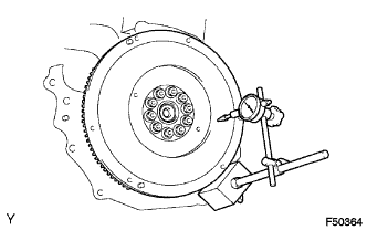
Using a dial indicator, inspect the flywheel sub-assembly runout.
Maximum runout 0.1 mm (0.004 in.) If the runout exceeds the maximum, replace the flywheel sub-assembly.
-
-
INSPECT CLUTCH RELEASE BEARING ASSEMBLY
-
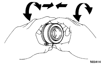
Check that the clutch release bearing assembly moves smoothly without abnormal resistance by turning the sliding parts of the clutch release bearing assembly (contact surfaces with the clutch cover) while applying force in the axial direction.
-
Inspect the clutch release bearing assembly for damage or wear.
-