CLUTCH PEDAL (for 1KD-FTV) INSTALLATION

-
INSTALL CLUTCH PEDAL SPRING HOLDER
-
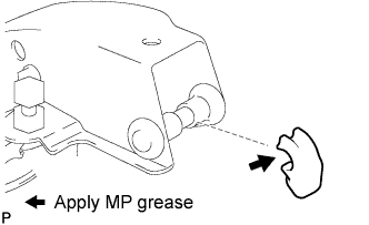
Apply MP grease to the inside of a new clutch pedal spring holder.
-
Install the clutch pedal spring holder.
-
-
INSTALL CLUTCH PEDAL PAD
-
Install the clutch pedal pad to the clutch pedal sub-assembly.
-
-
INSTALL CLUTCH PEDAL NO. 1 CUSHION
-
Using needle-nose pliers, install the clutch pedal No. 1 cushion to the clutch pedal sub-assembly.
-
-
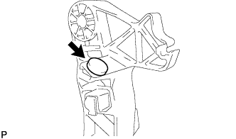
INSTALL CLUTCH PEDAL SHAFT COLLAR
-
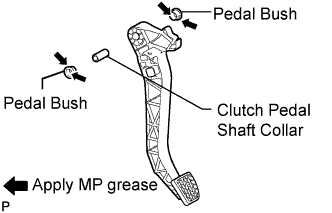
Apply MP grease to the inner, outer and end surfaces of 2 new pedal bushes.
-
Install the clutch pedal shaft collar and 2 pedal bushes to the clutch pedal sub-assembly.
-
-
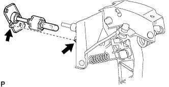
INSTALL CLUTCH PEDAL SUB-ASSEMBLY
-
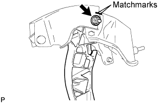
Align the matchmarks on the clutch pedal support sub-assembly.
-
Install the clutch pedal sub-assembly to the clutch pedal support sub-assembly with the bolt, washer and nut.
- Torque:
- 34 N*m { 350 kgf*cm, 25 ft.*lbf }
Tech Tips
Hold the nut and tighten the bolt.
-
-
INSTALL TURNOVER SPRING SEAT COMPRESSION SPRING
-
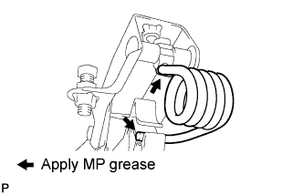
Apply MP grease to the sliding portion of the turnover spring seat compression spring.
-
Install the turnover spring seat compression spring.
-
-
INSTALL CLUTCH PEDAL SPRING
-
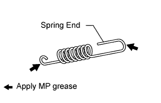
Apply MP grease to the sliding portion of the clutch pedal spring.
-
Install the clutch pedal spring.
Note
Be sure to install the clutch pedal spring with its end facing upward.
-
Install a new E-ring.
-
-
INSTALL CLUTCH SWITCH ASSEMBLY
-
Using a 14 mm union nut wrench, install the clutch switch assembly.
- Torque:
- 16 N*m { 160 kgf*cm, 12 ft.*lbf }
Note
Use the formula to calculate special torque values for situations where a union nut wrench is combined with a torque wrench Click here.
-
Connect the clutch switch connector.
-
-
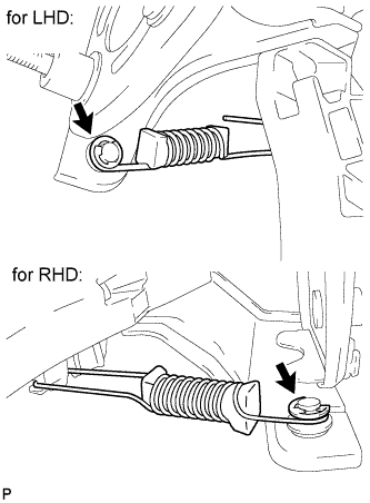
INSTALL CLUTCH PEDAL SUPPORT SUB-ASSEMBLY
-
Align the clip of the clutch pedal support with the hole of the bracket on the vehicle, and install the clutch pedal support sub-assembly.
Note
Make sure that the clip of the clutch pedal support is securely engaged in the hole of the bracket on the vehicle.
-
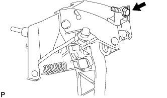
Install the clutch pedal support sub-assembly with the bolt.
- Torque:
- 31 N*m { 316 kgf*cm, 23 ft.*lbf }
-
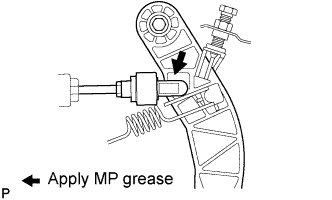
Apply MP grease to the sliding portions of the push rod clevis and clutch pedal sub-assembly.
-
Install the push rod clevis to the cutout of the clutch pedal sub-assembly from the right side of the vehicle and push it downward.
Note
Check that the push rod cannot be turned 30° or more in order to confirm that the clevis is securely engaged to the clutch pedal sub-assembly.
-
Connect the clutch switch connector and attach the wire harness clamp.
-
-
INSTALL CLUTCH MASTER CYLINDER ASSEMBLY
-
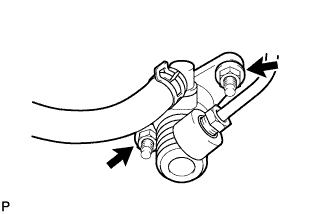
Install the clutch master cylinder with the 2 nuts.
- Torque:
- 14 N*m { 145 kgf*cm, 10 ft.*lbf }
-
-
INSPECT AND ADJUST CLUTCH PEDAL HEIGHT
-
INSTALL NO. 1 AIR DUCT
-
INSTALL WINDSHIELD WASHER MOTOR AND PUMP ASSEMBLY (for LHD)
-
Install the windshield washer motor and pump with the 2 bolts.
- Torque:
- 4.9 N*m { 50 kgf*cm, 43 in.*lbf }
-
-
INSTALL LOWER CENTER INSTRUMENT PANEL FINISH PANEL
-
Engage the 8 claws and install the instrument panel finish panel lower center.
-
-
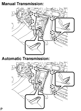
INSTALL SHIFTING HOLE COVER ASSEMBLY
-
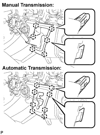
Manual Transmission:
Engage the 6 claws and install the shifting hole cover assembly.
-
Automatic Transmission:
Engage the 8 claws and install the sifting hole cover assembly.
-
-
INSTALL SHIFT LEVER KNOB
-
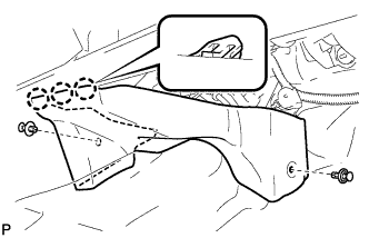
INSTALL PARKING BRAKE HOLE COVER
-
Engage the 6 claws and install the parking brake hole cover.
-
-
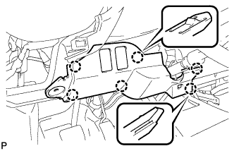
INSTALL NO. 1 INSTRUMENT PANEL UNDER COVER SUB-ASSEMBLY
-
Engage the 3 claws.
-
Install the instrument panel No.1 under cover sub-assembly with the 2 clips.
-
-
INSTALL LOWER INSTRUMENT PANEL FINISH PANEL
-
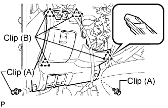
Engage the 4 clips (B).
-
Install the instrument panel finish panel lower with the 2 clips (A).
-
-
CONNECT CABLE TO NEGATIVE BATTERY TERMINAL
- Torque:
- 5.4 N*m { 55 kgf*cm, 47 in.*lbf }
-
PERFORM INITIALIZATION
Some systems need initialization when disconnecting the cable from the negative battery terminal. Click here