SHIFT LEVER ASSEMBLY INSTALLATION

Tech Tips
-
Use the same procedure for RHD and LHD vehicles.
-
The procedure listed below is for LHD vehicles.
-
INSTALL SHIFT LOCK CONTROL UNIT ASSEMBLY
-
Install the shift lock control unit assembly with the 4 bolts.
- Torque:
- 14 N*m { 138 kgf*cm, 10 ft.*lbf }
-
Connect the clamp and 2 connectors to the shift lock control unit assembly.
-
-
INSTALL TRANSMISSION CONTROL CABLE ASSEMBLY
-
Turn the nut of the transmission control cable assembly approximately 180° counterclockwise. While holding the nut in place, securely push the stopper in all the way.
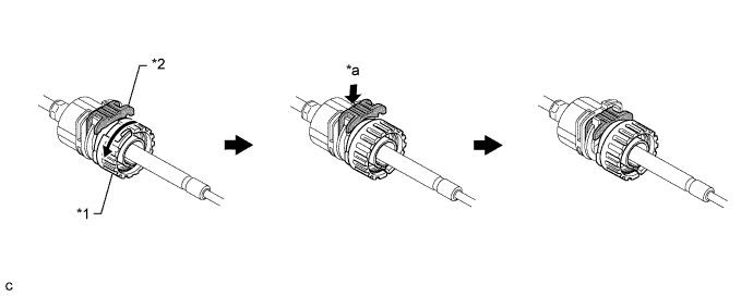
Text in Illustration *1 Stopper *2 Nut *a Push in - - Note
Do not over-rotate the nut as it will come off the internal spring and the transmission control cable assembly will not be reusable.
-
Install the outer part of the transmission control cable assembly to the shift lock control unit assembly. Check that the spring is positioned at "A" and push in the stopper.
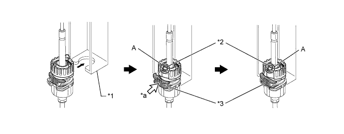
Text in Illustration *1 Shift Lock Control Unit Assembly *2 Spring *3 Stopper - - *a Push in - - Note
Ensure that the groove on the transmission control cable assembly is securely fitted to the shift lock control unit assembly.
Tech Tips
If the stopper cannot be pushed in, slightly turn the nut clockwise and then push in the stopper again.
-
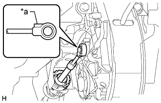
Text in Illustration *a Protrusion Connect the end of the transmission control cable assembly to the shift lock control unit assembly.
Note
-
Securely connect the cable end until if fits securely against the base of the pin.
-
Connect the cable end with the protrusion facing the front of the vehicle.
-
-
-
INSTALL INSTRUMENT PANEL FINISH PANEL LOWER CENTER
-
Attach the 8 claws to install the instrument panel finish panel lower center.
-
-
INSTALL PARKING BRAKE HOLE COVER
-
Attach the 6 claws to install the parking brake hole cover.
-
-
INSTALL INSTRUMENT PANEL FINISH PANEL LOWER
-
Connect the fuel lid lock control cable and bonnet (hood) control cable assembly to the instrument panel finish lower.
-
Attach the 4 clips to install the instrument panel finish panel lower.
-
Install the 2 clips.
-
-
INSTRUMENT PANEL UNDER COVER SUB-ASSEMBLY NO.1
-
Attach the 3 claws to instrument panel under cover sub-assembly No. 1.
-
Install the the 2 clips.
-
-
INSTALL FLOOR SHIFT POSITION INDICATOR HOUSING SUB-ASSEMBLY
-
Attach the 8 claws to install the floor shift position indicator housing sub-assembly.
-
-
INSTALL SHIFT LEVER CAP
-
Attach the 2 claws to install the shift lever cap to the floor shift position indicator housing sub-assembly.
-
-
INSTALL SHIFT LEVER KNOB
-
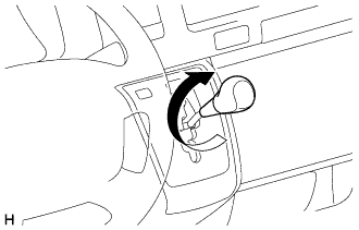
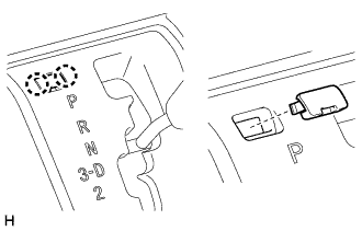
Install the shift lever knob and twist it in the direction indicated by the arrow.
-
-
ADJUST SHIFT LEVER POSITION
-
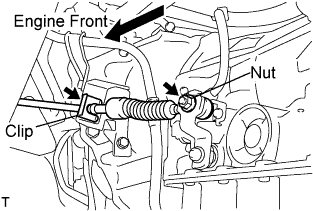
Remove a clip, nut, and disconnect between the control shaft lever to transmission control cable assembly from the control shaft lever and transmission control cable bracket No.1.
-
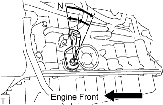
Turn the control shaft lever until stop to a clockwise direction, return the control shaft lever 2 notches to N position.
-

Set the shift lever to N position while holding the shift lever lightly toward the R position side and install it.
- Torque:
- 15 N*m { 150 kgf*cm, 11 ft.*lbf }
Note
Tighten the nut with it closing up cranky.
-
Inspect the operation condition and work.
-
-
INSPECT SHIFT LEVER POSITION
-
When shifting from P position only with ignition switch ON and depress the break pedal.
-
Make sure that the shifting lever moves smoothly and can be moderately operated.
-
When starting engine, make sure that the vehicle moves forward when shifting from N to D position and moves reward when shifting R position.
-