FORWARD CLUTCH (for 1KD-FTV) DISASSEMBLY

-
FIX FORWARD CLUTCH ASSEMBLY
-
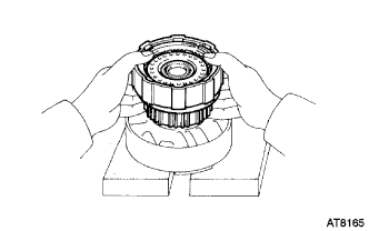
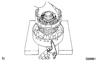
Place wooden blocks, etc., to prevent the input shaft sub-assembly from touching the work stand, and place the overdrive support sub-assembly on them.
-
Place the forward clutch assembly onto the overdrive support sub-assembly.
-
-
INSPECT PISTON STROKE OF FORWARD CLUTCH
-
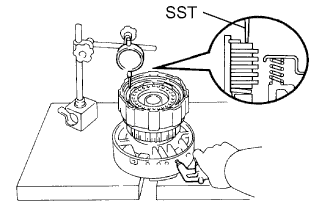
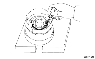
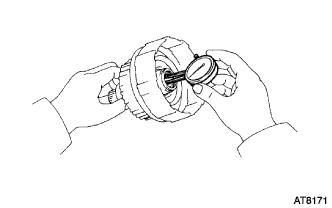
Using SST and a dial indicator, measure the forward clutch piston stroke while applying and releasing compressed air (392 kPa, 4.0 kgf/cm2, 57 psi).
- SST
- 09350-30020 ( 09350-06120 )
Piston stroke 0.60 to 1.00 mm (0.0236 to 0.0394 in.) If the piston stroke is less than the limit, parts may be assembled incorrectly, so inspect and reassemble them if necessary.
If the piston stroke is outside the standard range, select another flange.
Tech Tips
There are 8 different flanges in thickness.
Flange thickness No. Thickness
mm (in.)
No. Thickness
mm (in.)
90 3.0 (0.118) 94 3.8 (0.150) 91 3.2 (0.126) 95 4.0 (0.157) 92 3.4 (0.134) 96 4.2 (0.165) 93 3.6 (0.142) 97 4.4 (0.173)
-
-
REMOVE FORWARD MULTIPLE DISC CLUTCH CLUTCH DISC
-
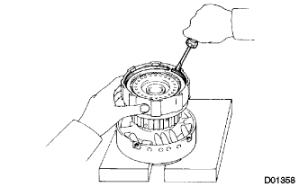
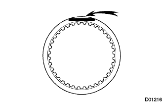
Using a screwdriver, remove the snap ring from the forward clutch assembly.
Tech Tips
Tape up the screwdriver tip before use.
-
Remove the flange, the 6 plates and the 6 discs.
-
Remove the cushion plate.
-
-
INSPECT FORWARD MULTIPLE DISC CLUTCH CLUTCH DISC
-
Check if the sliding surface of the disc, the plate and flange are worn or burnt. If necessary, replace them.
Tech Tips
-
If the lining of the disc is peeled off or discolored, or even if only a part of the printed numbers is corroded, replace all discs.
-
Before assembling new discs, soak them in ATF for at least 15 minutes.
-
-
-
REMOVE FORWARD CLUTCH RETURN SPRING SUB-ASSEMBLY
-
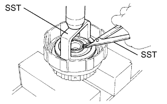
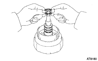
Place SST on the spring retainer, and compress the forward clutch return spring sub-assembly with a press.
- SST
- 09350-30020 ( 09350-07040 )
-
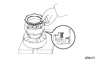
Using SST, remove the snap ring.
- SST
- 09350-30020 ( 09350-07070 )
-
Remove the forward clutch return spring sub-assembly.
-
-
REMOVE FORWARD CLUTCH PISTON SUB-ASSEMBLY
-
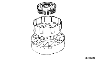
Place the forward clutch assembly onto the overdrive support sub-assembly.
-
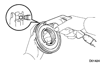
While holding the forward clutch piston sub-assembly apply compressed air (196 kPa, 2.0 kgf/cm2, 28.5 psi) to the overdrive support sub-assembly.
-
Remove the forward clutch piston sub-assembly.
-
Remove the O-ring.
-
-
REMOVE FORWARD CLUTCH PISTON O-RING
-
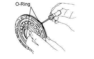
Using a small screwdriver, remove the 2 O-rings.
-
-
INSPECT FORWARD CLUTCH PISTON SUB-ASSEMBLY
-
Check that the check ball is moves freely by shaking the piston.
-
Check that the valve does not have leaks by applying low-pressure compressed air.
-
-
REMOVE INPUT SHAFT OIL SEAL RING
-
Remove the 3 input shaft oil seal rings from the input shaft sub-assembly.
-
-
INSPECT INPUT SHAFT SUB-ASSEMBLY
-
Using a dial indicator, measure the inside diameter of the input shaft sub-assembly bushing.
Maximum inside diameter 24.08 mm (0.9480 in.) If the inside diameter is greater than the maximum, replace the input shaft sub-assembly.
-