VALVE BODY ASSEMBLY INSPECTION

-
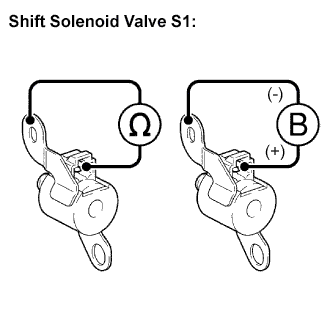
INSPECT SHIFT SOLENOID VALVE S1
-
Remove the shift solenoid valve S1.
-
Measure the resistance according to the value(s) in the table below.
Resistance: Tester Connection Specified Condition 20°C (68°F) Solenoid Connector (S1) - Solenoid Body (S1) 11 to 15 Ω -
Connect the positive (+) lead to the terminal of the solenoid connector, and the negative (-) lead to the solenoid body.
OK The solenoid makes an operating sound.
-
-
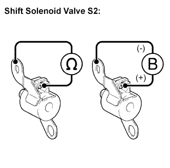
INSPECT SHIFT SOLENOID VALVE S2
-
Remove the shift solenoid valve S2.
-
Measure the resistance according to the value(s) in the table below.
Resistance: Tester Connection Specified Condition 20°C (68°F) Solenoid Connector (S2) - Solenoid Body (S2) 11 to 15 Ω -
Connect the positive (+) lead to the terminal of the solenoid connector, and the negative (-) lead to the solenoid body.
OK The solenoid makes an operating sound.
-
-
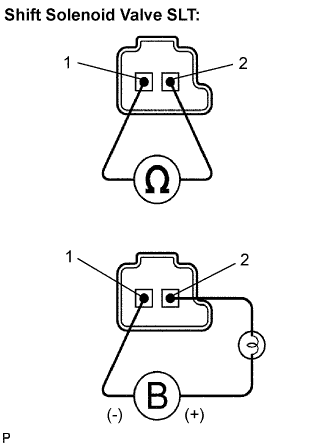
INSPECT SHIFT SOLENOID VALVE SLT
-
Remove the shift solenoid valve (SLT).
-
Measure the resistance according to the value(s) in the table below.
Resistance: Tester Connection Specified Condition 20°C (68°F) 1 - 2 5.0 to 5.6 Ω -
Connect the positive (+) lead with a 21 W bulb to terminal 2 and the negative (-) lead to terminal 1 of the solenoid valve connector, then check the movement of the valve.
OK The solenoid makes an operating sound.
-