ELECTRONIC CONTROLLED AUTOMATIC TRANSMISSION SYSTEM, Diagnostic DTC:P2716/77

| DTC Code | DTC Name |
|---|---|
| P2716/77 | Pressure Control Solenoid "D" Electrical (Shift Solenoid Valve SLT) |
DESCRIPTION
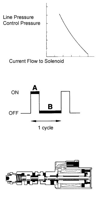
The linear solenoid valve (SLT) controls the transmission line pressure for smooth transmission operation based on signals from the throttle position sensor and the vehicle speed sensor.
The TCM adjusts the duty cycle of the SLT solenoid valve to control hydraulic line pressure coming from the primary regulator valve. Appropriate line pressure assures smooth shifting with varying engine outputs.
(*): Duty Ratio
The duty ratio is the ratio of the period of continuity in one cycle.
For example, if A is the period of continuity in one cycle, and B is the period of non-continuity, then
Duty Ratio = A/(A + B) x 100 (%)
| DTC No. | DTC Detection Condition | Trouble Area |
|---|---|---|
| P2716/77 | Open or short is detected in shift solenoid valve SLT circuit for 1 second or more while driving (1-trip detection logic). |
|
MONITOR DESCRIPTION
When an open or short in the linear solenoid valve (SLT) circuit is detected, the TCM interprets this as a fault.
The TCM will turn on the MIL and store the DTC.
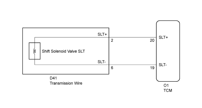
WIRING DIAGRAM
INSPECTION PROCEDURE
PROCEDURE
-
INSPECT TRANSMISSION WIRE (SLT)
-
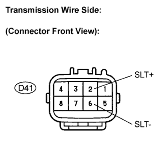
Disconnect the transmission wire connector from the transmission.
-
Measure the resistance according to the value(s) in the table below.
Resistance Tester Connection Specified Condition
20°C (68°F)
2 (SLT+) - 6 (SLT-) 5.0 to 5.6 Ω -
Measure the resistance according to the value(s) in the table below.
Resistance (Check for short) Tester Connection Specified Condition 2 (SLT+) - Body ground 10 kΩ or higher 6 (SLT-) - Body ground ↑
NG 
INSPECT SHIFT SOLENOID VALVE SLT Click here
OK 
-
-
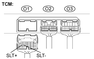
CHECK HARNESS AND CONNECTOR (TRANSMISSION WIRE - TCM)
-
Connect the transmission wire connector to the transmission.
-
Disconnect the TCM connector.
-
Measure the resistance according to the value(s) in the table below.
Resistance Tester Connection Specified Condition
20°C (68°F)
O1-20 (SLT+) - O1-19 (SLT-) 5.0 to 5.6 Ω -
Measure the resistance according to the value(s) in the table below.
Resistance (Check for short) Tester Connection Specified Condition O1-20 (SLT+) - Body ground 10 kΩ or higher O1-19 (SLT-) - Body ground ↑
NG 
REPAIR OR REPLACE HARNESS OR CONNECTOR
OK 
REPLACE TCM
-
-
INSPECT SHIFT SOLENOID VALVE SLT
-
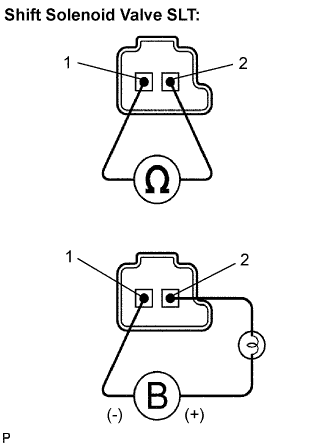
Remove the shift solenoid valve (SLT).
-
Measure the resistance according to the value(s) in the table below.
Resistance Tester Connection Specified Condition
20°C (68°F)
1 - 2 5.0 to 5.6 Ω -
Connect the positive (+) lead with a 21 W bulb to terminal 2 and the negative (-) lead to terminal 1 of the solenoid valve connector, then check the movement of the valve.
OK The solenoid makes an operating sound.
NG
REPLACE SHIFT SOLENOID VALVE SLT
OK
REPAIR OR REPLACE TRANSMISSION WIRE
-