ELECTRONIC CONTROLLED AUTOMATIC TRANSMISSION SYSTEM Stop Light Switch Circuit
DESCRIPTION
The purpose of this circuit is to prevent the engine from stalling while driving in lock-up condition when brakes are suddenly applied.
When the brake pedal is depressed, this switch sends a signal to the TCM. Then the TCM cancels the operation of the lock-up clutch while braking is in progress.
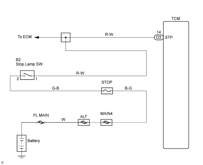
WIRING DIAGRAM
INSPECTION PROCEDURE
PROCEDURE
-
READ VALUE USING DATA LIST (STP SIGNAL)
-
DATA LIST
Tech Tips
Using the Intelligent Tester Data List allows switch, sensor, actuator and other item values to be read without removing any parts. Reading the Data List early in troubleshooting is one way to shorten labor time.
-
Turn the ignition switch off.
-
Connect the Intelligent Tester to the DLC3.
-
Turn the ignition switch to the ON position.
-
Turn on the tester.
-
Select the item "Enter / Power train / ECT / Data List".
-
Follow the instructions on the tester and read the Data List.
Standard Item Measurement Item /
Range (display)
Normal Condition Stop Light Switch Stop light SW Status/
ON or OFF
-
Brake Pedal is depressed: ON
-
Brake Pedal is released: OFF
Note
In the table above, the conditions listed under "Normal Condition" are reference conditions. Do not depend solely on these reference conditions when deciding whether a part is faulty or not.
-
-
OK 
CHECK HARNESS AND CONNECTOR (STOP LIGHT SWITCH ASSEMBLY - TCM) Click here
NG 
-
-
INSPECT STOP LIGHT SWITCH ASSEMBLY
-
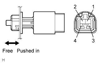
Remove the stop light switch assembly.
-
Measure the resistance according to the value(s) in the table below.
Resistance Switch position Tester Condition Specified Condition Switch pin free 1 - 2 Below 1 Ω Switch pin pushed in ↑ 10 kΩ or higher Switch pin free 3 - 4 10 kΩ or higher Switch pin pushed in ↑ Below 1 Ω
NG 
REPLACE STOP LIGHT SWITCH ASSEMBLY
OK
-
-
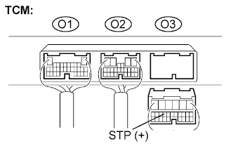
CHECK HARNESS AND CONNECTOR (STOP LIGHT SWITCH ASSEMBLY - TCM)
-
Install the stop light switch assembly.
-
Disconnect the TCM connector.
-
Measure the voltage according to the value(s) in the table below when the brake pedal is depressed and released.
Voltage Condition Tester Condition Specified Condition Brake pedal is depressed O3-14 (STP) - Body ground 10 to 14 V Brake pedal is released ↑ Below 1 V
NG
REPAIR OR REPLACE HARNESS OR CONNECTOR
OK 
PROCEED TO NEXT CIRCUIT INSPECTION SHOWN IN PROBLEM SYMPTOMS TABLE
-