ELECTRONIC CONTROLLED AUTOMATIC TRANSMISSION SYSTEM Park / Neutral Position Switch Circuit
DESCRIPTION
The park/neutral position switch detects the shift lever position and sends signals to the TCM.
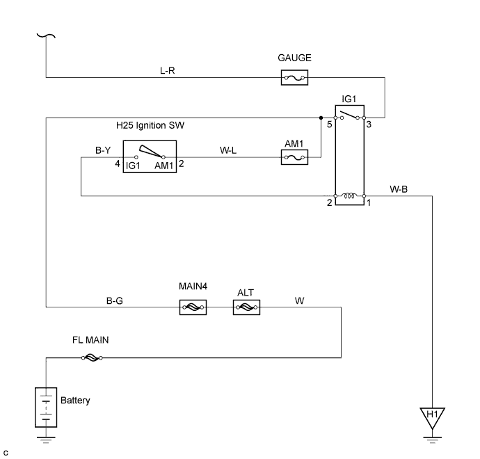
WIRING DIAGRAM
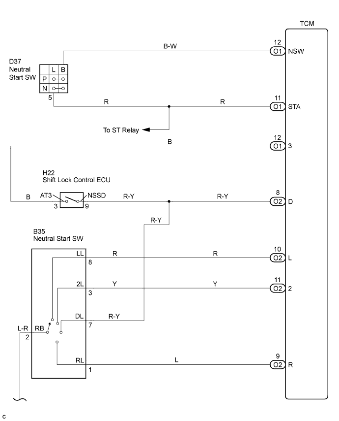
INSPECTION PROCEDURE
-
DATA LIST
Tech Tips
Using the Intelligent Tester Data List allows switch, sensor, actuator and other item values to be read without removing any parts. Reading the Data List early in troubleshooting is one way to shorten labor time.
Note
In the table below, the values listed under "Normal Condition" are reference values. Do not depend solely on these reference values when deciding whether a part is faulty or not.
-
Warm up the engine.
-
Turn the ignition switch off.
-
Connect the Intelligent Tester to the DLC3.
-
Turn the ignition switch to the ON position.
-
Turn on the tester.
-
Select the item "Enter / Power train / ECT / Data List".
-
Follow the instructions on the tester and read the Data List.
Item Measurement Item/
Range (display)
Normal Condition Diagnostic Note Neutral Position SW Signal PNP SW Status/
ON or OFF
Shift lever position is;
P and N: ON
Except P and N: OFF
When the shift lever position displayed on the Intelligent tester differs from the actual position, adjustment of the PNP switch or the shift cable may be incorrect. Shift SW Status (L Range) PNP SW Status/
ON or OFF
Shift lever position is;
L: ON
Except L: OFF
↑ Shift SW Status (2 Range) PNP SW Status/
ON or OFF
Shift lever position is;
2 and L: ON
Except 2 and L: OFF
↑ Shift SW Status (3 Range) PNP SW Status/
ON or OFF
Shift lever position is;
3: ON
Except 3: OFF
↑ Shift SW Status (R Range) PNP SW Status/
ON or OFF
Shift lever position is;
R: ON
Except R: OFF
↑ Shift SW Status (D Range) PNP SW Status/
ON or OFF
Shift lever position is;
D and 3: ON
Except D and 3: OFF
↑ Tech Tips
Start the inspection from the step 1 when the malfunction is found in the 3 position, and start from step 2 when the malfunction is in the other position.
-
PROCEDURE
-
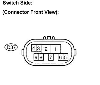
INSPECT PARK/NEUTRAL POSITION SWITCH ASSEMBLY
-
Jack up the vehicle.
-
Disconnect the park/neutral position switch connector.
-
Measure the resistance according to the value(s) in the table below when the shift lever is moved to each position.
Resistance Shift Position Tester Connection Specified Condition P 2 - 6 and 4 - 5 Below 1 Ω Except P ↑ 10 kΩ or higher R 2 - 1 Below 1 Ω Except R ↑ 10 kΩ or higher N 2 - 9 and 4 - 5 Below 1 Ω Except N ↑ 10 kΩ or higher D and 3 2 - 7 Below 1 Ω Except D and 3 ↑ 10 kΩ or higher 2 2 - 3 Below 1 Ω Except 2 ↑ 10 kΩ or higher L 2 - 8 Below 1 Ω Except L ↑ 10 kΩ or higher
NG 
REPLACE PARK/NEUTRAL POSITION SWITCH ASSEMBLY
OK 
-
-
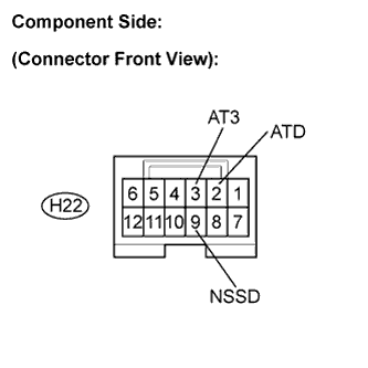
INSPECT SHIFT LOCK CONTROL UNIT ASSEMBLY
-
Connect the park/neutral position switch connector.
-
Disconnect the transmission control switch connector of shift lock control unit assembly.
-
Measure the resistance according to the value(s) in the table below when the shift lever is moved to each position.
Resistance Shift position Tester connection Specified condition D 9 - 2 (NSSD - ATD) Below 1 Ω 3 10 kΩ or higher D 9 - 3 (NSSD - AT3) 10 kΩ or higher 3 Below 1 Ω
NG
REPLACE SHIFT LOCK CONTROL UNIT ASSEMBLY
OK
-
-
CHECK HARNESS AND CONNECTOR (PARK/NEUTRAL POSITION SWITCH - TCM)
-
Connect the transmission control switch connector of shift lock control unit assembly.
-
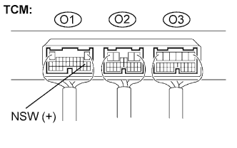
Turn the ignition switch to the ON position, and measure the voltage according to the value(s) in the table below when the shift lever is moved to each position.
Voltage Shift Position Tester connection Specified condition P and N O1-12 (NSW) - Body ground Below 2 V Except P and N ↑ 10 to 14 V
NG
REPAIR OR REPLACE HARNESS OR CONNECTOR
OK
-
-
CHECK HARNESS AND CONNECTOR (PARK/NEUTRAL POSITION SWITCH - TCM)
-
Disconnect the TCM connector.
-
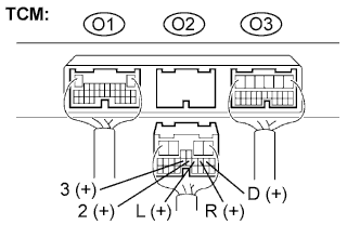
Turn the ignition switch to the ON position, and measure the voltage according to the value(s) in the table below when the shift lever is moved to each position.
Voltage Shift Position Tester connection Specified condition R O2-9 (R) - Body ground 10 to 14 V* Except R ↑ Below 1 V D and 3 O2-8 (D) - Body ground 10 to 14 V Except D and 3 ↑ Below 1 V 3 O2-12 (3) - Body ground 10 to 14 V Except 3 ↑ Below 1 V 2 O2-11 (2) - Body ground 10 to 14 V Except 2 ↑ Below 1 V L O2-10 (L) - Body ground 10 to 14 V Except L ↑ Below 1 V Tech Tips
*: The voltage will drop slightly due to the turning on of the back up light.
NG
REPAIR OR REPLACE HARNESS OR CONNECTOR
OK 
PROCEED TO NEXT CIRCUIT INSPECTION SHOWN IN PROBLEM SYMPTOMS TABLE
-