AUTOMATIC TRANSMISSION ASSEMBLY REMOVAL

-
PRECAUTION
Note
After turning the ignition switch off, waiting time may be required before disconnecting the cable from the battery terminal. Therefore, make sure to read the disconnecting the cable from the battery terminal notice before proceeding with work Click here.
-
DISCONNECT CABLE FROM NEGATIVE BATTERY TERMINAL
Note
When disconnecting the cable, some systems need to be initialized after the cable is reconnected Click here
-
REMOVE TRANSMISSION OIL LEVEL GAUGE SUB-ASSEMBLY
-
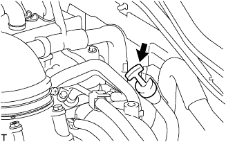
Remove the transmission oil level gauge sub-assembly.
-
-
REMOVE NO. 1 ENGINE UNDER COVER
-
DRAIN AUTOMATIC TRANSMISSION FLUID
-
Remove the drain plug and gasket, and drain the ATF.
-
Install a new gasket and the drain plug.
- Torque:
- 20 N*m { 205 kgf*cm, 15 ft.*lbf }
-
-
REMOVE PROPELLER SHAFT ASSEMBLY
-
REMOVE STARTER ASSEMBLY
-
REMOVE FRONT EXHAUST PIPE ASSEMBLY
-
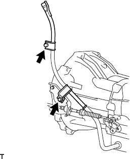
DISCONNECT TRANSMISSION CONTROL CABLE ASSEMBLY
-
Remove the nut and disconnect the transmission control cable assembly from the transmission control shaft lever LH.
-
Remove the clip and disconnect the transmission control cable assembly from the transmission control cable bracket.
-
-
REMOVE TRANSMISSION CONTROL CABLE BRACKET
-
Remove the 2 bolts and transmission control cable bracket from the automatic transmission assembly.
-
-
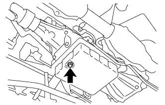
REMOVE TRANSMISSION OIL FILLER TUBE SUB-ASSEMBLY
-
Remove the 2 bolts and transmission oil filler tube sub-assembly.
-
Remove the O-ring from the transmission oil filler tube sub-assembly.
-
-
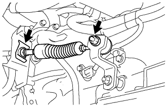
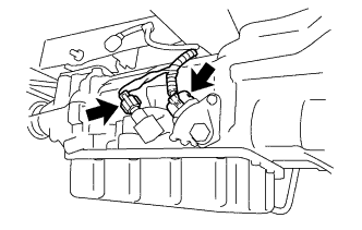
DISCONNECT OIL COOLER TUBE
-
Remove the 6 bolts and disconnect the 3 clamps.
-
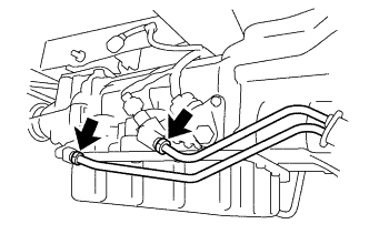
Using a union nut wrench, disconnect the 2 oil cooler tubes from the automatic transmission assembly.
-
-
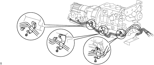
DISCONNECT WIRE HARNESS
-
Disconnect the park/neutral position switch assembly connector and ATF temperature sensor connector.
-
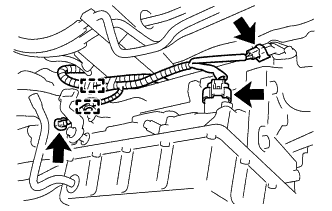
Disconnect the 2 speed sensor connectors and transmission wire connector.
-
Detach the 2 clamps and disconnect the wire harness from the automatic transmission assembly.
-
-
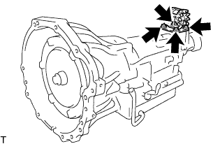
REMOVE DRIVE PLATE AND TORQUE CONVERTER SETTING BOLT
-
Remove the flywheel housing dust seal.
-
Turn the crankshaft to gain access to the 6 drive plate and torque converter setting bolts and remove each bolt while holding the crankshaft pulley bolt with a wrench.
-
-
SUPPORT AUTOMATIC TRANSMISSION ASSEMBLY
-
Support the automatic transmission assembly with a transmission jack.
Note
-
In order to protect the automatic transmission oil pan sub-assembly, place attachments on the transmission jack.
-
Make sure that the attachments and the automatic transmission oil pan sub-assembly are centered on the transmission jack.
-
To prevent the automatic transmission oil pan sub-assembly from deforming, do not place any attachments under the automatic transmission oil pan sub-assembly of the automatic transmission assembly.
-
-
-
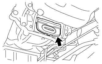
DISCONNECT REAR ENGINE MOUNTING INSULATOR ASSEMBLY
-
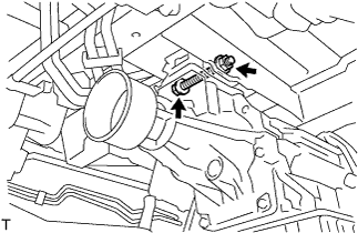
Remove the bolt, nut and 2 washers and disconnect the rear engine mounting insulator assembly.
-
-
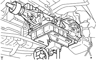
REMOVE AUTOMATIC TRANSMISSION ASSEMBLY
-
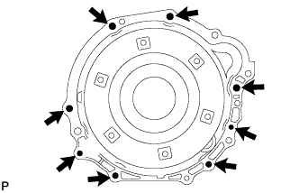
Remove the 8 bolts and automatic transmission assembly from the engine assembly.
Note
-
Secure the automatic transmission assembly to the transmission jack using a belt, etc. to prevent it from falling.
-
To prevent damage to the knock pins, do not pry between the automatic transmission assembly and engine assembly.
-
-
-
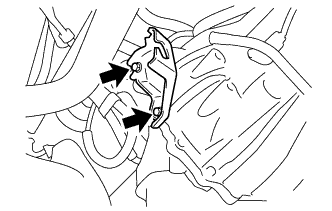
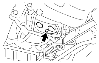
REMOVE REAR ENGINE MOUNTING INSULATOR ASSEMBLY
-
Remove the 4 bolts and rear engine mounting insulator assembly from the automatic transmission assembly.
-
-
REMOVE TORQUE CONVERTER ASSEMBLY
-
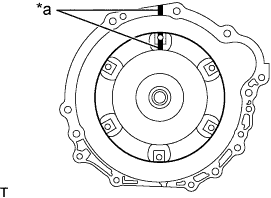
Text in Illustration *a Matchmark Put matchmarks on the case and the torque converter assembly.
-
Remove the torque converter assembly from the automatic transmission assembly.
Note
Remove the torque converter assembly from the input shaft horizontally.
-
-
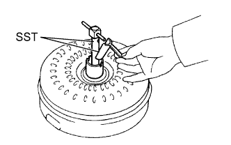
INSPECT TORQUE CONVERTER ASSEMBLY
-
Inspect the one-way clutch.
-
Install SST to the inner race of the one-way clutch.
- SST
- 09350-32014 ( 09351-32010 )
-
Set SST so that it fits in the notch of the torque converter hub and the outer race of the one-way clutch.
- SST
- 09350-32014 ( 09351-32020 )
-
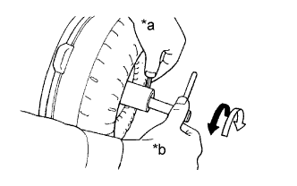
Text in Illustration *a Hold *b Turn 
Difficult 
Smooth With the torque converter assembly standing on its side, check that the clutch locks when SST is turned counterclockwise and rotates freely and smoothly when SST is turned clockwise.
If the results are not as specified, clean the torque converter assembly and recheck the one-way clutch.
If the results still are not as specified even after cleaning the torque converter assembly, replace the torque converter assembly.
-
-
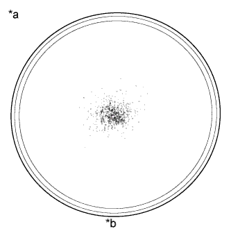
Text in Illustration *a Sample showing maximum allowable amount of powder in ATF *b Full Scale Determine the condition of the torque converter assembly.
-
A metallic sound is emitted from the torque converter assembly during the stall test or when the shift lever is moved to N.
-
The one-way clutch turns smoothly or is locked in both directions.
-
The amount of powder in the ATF is more than the sample shown in the illustration (refer to the sample).
-
Check that the following conditions are met:
-
During the stall test or when the shift lever is in N, metallic sounds are not emitted from the torque converter assembly.
-
The one-way clutch turns in one direction and locks in the other direction.
-
The amount of powder in the ATF is not more than the sample shown in the illustration.
If the results are not as specified, replace the torque converter assembly.
Tech Tips
The sample illustration shows approximately 0.025 liters (0.026 US qts, 0.022 Imp. qts) of ATF taken from a removed torque converter assembly.
-
-
-
Replace the ATF in the torque converter assembly.
-
If the ATF is discolored and/or has a foul odor, stir the ATF in the torque converter assembly thoroughly and drain the ATF with the torque converter assembly facing upward.
-
-
Clean and check the oil pipe line.
-
If the torque converter assembly is inspected or the ATF is replaced, clean the oil pipe line.
Tech Tips
-
Apply 196 kPa (2 kgf/cm2, 28 psi) of compressed air to the inlet hose.
-
If a large amount of powder is found in the ATF, add new ATF using a bucket pump and clean the oil pipe line again.
-
-
If the ATF is cloudy, inspect the radiator.
-
-
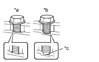
Text in Illustration *a Correct *b Incorrect *c Bottom is damaged Prevent deformation of the torque converter assembly and damage to the oil pump gear.
Note
Make sure that all of the bolts are the same length and that the specified bolts are used.
Tech Tips
If there is any damage to the tip of a bolt for the torque converter assembly or to the bottom of a bolt hole, replace the bolt and torque converter assembly.
-