GENERATOR INSTALLATION

-
INSTALL GENERATOR ASSEMBLY
-
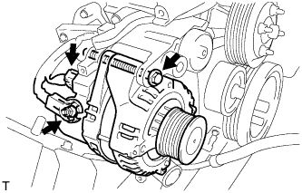
Install the generator assembly with the bolt.
- Torque:
- 62 N*m { 632 kgf*cm, 46 ft.*lbf }
-
Install the generator wire to terminal B with the nut.
- Torque:
- 9.8 N*m { 100 kgf*cm, 87 in.*lbf }
-
Install the terminal cap.
-
Connect the generator connector.
-
-
INSTALL GENERATOR BRACKET
-
Install the generator bracket with the 2 bolts.
- Torque:
- 36 N*m { 367 kgf*cm, 27 ft.*lbf }
-
-
INSTALL IDLE NO.2 PULLEY ASSEMBLY (w/ Air Conditioning System)
-
Install the idle No.2 pulley assembly and washer with the bolt.
- Torque:
- 45 N*m { 459 kgf*cm, 33 ft.*lbf }
-
-
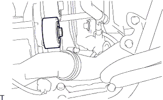
INSTALL AIR CLEANER HOSE ASSEMBLY
-
Install the air cleaner hose assembly with the clamp.
-
-
INSTALL AIR TUBE ASSEMBLY
-
Install the air tube assembly with the 2 clamps and 2 bolts.
-
-
INSTALL VENTILATION PIPE
-
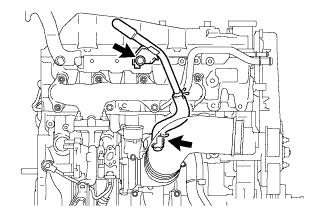
Install the ventilation pipe with the bolt and clip.
- Torque:
- 20 N*m { 204 kgf*cm, 15 ft.*lbf }
-
-
INSTALL COMPRESSOR OUTLET ELBOW
-
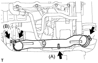
Install the compressor outlet elbow with the 2 bolts and 2 clamps.
- Torque:
- Bolt (A)
- 12 N*m { 122 kgf*cm, 9 ft.*lbf }
- Bolt (B)
- 32 N*m { 326 kgf*cm, 24 ft.*lbf }
-
-
INSTALL COMPRESSOR AND MAGNETIC CLUTCH (w/ Air Conditioning System)
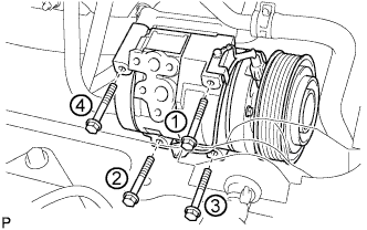
-
Provisionally tighten the compressor and magnetic clutch with the 4 bolts.
-
Tighten the compressor and magnetic clutch with the 4 bolts.
- Torque:
- 25 N*m { 255 kgf*cm, 18 ft.*lbf }
Note
Tighten the bolts in the order shown in the illustration to install the compressor and magnetic clutch.
-
-
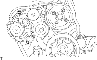
INSTALL FAN & GENERATOR V BELT
-
Rotate the V-ribbed belt tensioner pulley clockwise, and then install the fan and generator V belt.
Note
Make sure that the fan and generator V belt is set properly on each pulley.
-
Check that the indicator mark of the V-ribbed belt tensioner Click here.
-
-
INSTALL FENDER APRON MUDGUARD SEAL RH
-
INSTALL ENGINE SERVICE HOLE SUB COVER ASSEMBLY
-
Install the engine service hole sub cover with the 5 bolts.
- Torque:
- 13 N*m { 133 kgf*cm, 10 ft.*lbf }
-
-
INSTALL FRONT SEAT ASSEMBLY RH (for Hi-back Seat Type)
Tech Tips
Perform the same procedure as above on the opposite side. Click here
-
INSTALL FRONT SEAT ASSEMBLY RH (for Low-back Seat Type)
Tech Tips
Perform the same procedure as above on the opposite side. Click here
-
INSTALL FRONT DOOR SCUFF PLATE RH
-
CONNECT NEGATIVE BATTERY CABLE
-
INSTALL ENGINE UNDER COVER NO.1 (w/ Engine Under Cover No.1)
- Torque:
- 13 N*m { 133 kgf*cm, 10 ft.*lbf }
-
PERFORM INITIALIZATION
-
Some system need initialization when reconnecting the battery cable. Click here
-