STARTER (for 1.7 kW Type) INSPECTION

-
INSPECT STARTER ARMATURE ASSEMBLY
-
Inspect the commutator for an open circuit.
-
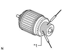
Text in Illustration *1 Segment Measure the resistance according to the value(s) in the table below.
Standard Resistance Tester Connection Connection Specified Condition Segment - Segment Always 2.7 to 3.3 Ω If the result is not as specified, replace the starter armature assembly.
-
-
Inspect the commutator for a short circuit.
-
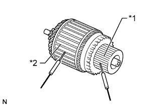
Text in Illustration *1 Segment *2 Coil Core Measure the resistance according to the value(s) in the table below.
Standard Resistance Tester Connection Connection Specified Condition Segment - Coil Core Always 10 kΩ or higher If the result is not as specified, replace the starter armature assembly.
-
-
Check the commutator for dirt and/or burns on the surface.
If the surface is dirty or burnt, correct it with sandpaper (No. 400) or a lathe.
-
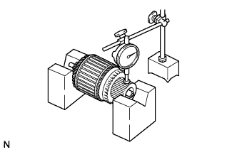
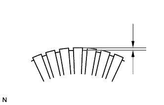
Check the commutator circle runout.
-
Place the commutator on V-blocks.
-
Using a dial indicator, measure the circle runout.
Standard circle runout 0.02 mm (0.000787 in.) Maximum circle runout 0.04 mm (0.00157 in.) If the runout is more than the maximum, replace the armature assembly.
-
-
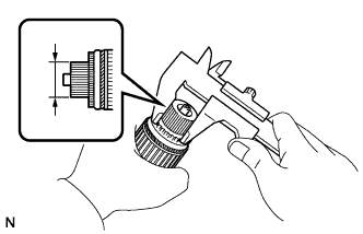
Using a vernier caliper, measure the commutator diameter.
Standard commutator diameter 32.2 mm (1.27 in.) Minimum commutator diameter 31.1 mm (1.22 in.) If the diameter is less than the minimum, replace the armature assembly.
-
Using a vernier caliper, measure the undercut depth of the commutator.
Standard undercut depth 0.9 mm (0.0354 in.) Minimum undercut depth 0.4 mm (0.0157 in.) If the undercut depth is less than the minimum, replace the armature assembly.
-
-
INSPECT STARTER BRUSH HOLDER ASSEMBLY
-
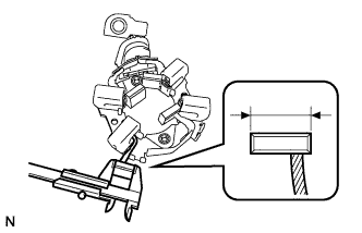
Using a vernier caliper, measure the brush length.
Standard brush length 11.3 mm (0.445 in.) Minimum brush length 7.5 mm (0.295 in.) If the length is less than the minimum, replace the brush holder assembly.
-
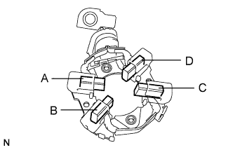
Check the brush holder.
-
Measure the resistance between the brushes.
Standard Resistance Tester Connection Specified Condition A - B 10 kΩ or higher A - C 10 kΩ or higher A - D Below 1 Ω B - C Below 1 Ω B - D 10 kΩ or higher C - D 10 kΩ or higher If the result is not as specified, replace the brush holder assembly.
-
-
-
INSPECT STARTER CLUTCH SUB-ASSEMBLY
-
Check the starter clutch pinion gear.
-
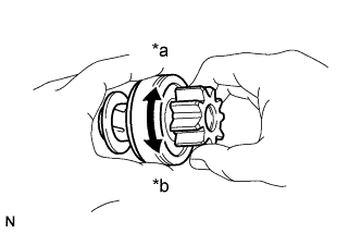
Text in Illustration *a Free *b Lock Rotate the pinion gear clockwise and check that it turns freely. Try to rotate the pinion gear counterclockwise and check that it locks.
If the result is not as specified, replace the starter clutch sub-assembly
-
-
-
INSPECT MAGNET STARTER SWITCH ASSEMBLY
-
Check the plunger.
-
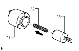
Text in Illustration *1 Switch Body *2 Spring *3 Plunger Install the plunger and spring onto the switch body.
-
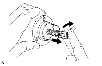
Push in the plunger and check that it returns quickly to its original position.
If the result is not as specified, replace the magnet starter switch assembly.
-
-
Inspect the pull-in coil.
-
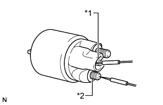
Text in Illustration *1 Terminal 50 *2 Terminal C Measure the resistance according to the value(s) in the table below.
Standard Resistance Tester Connection Connection Specified Condition Terminal 50 - Terminal C Always Below 1 Ω If the result is not as specified, replace the magnet starter switch assembly.
-
-
Inspect the holding coil.
-
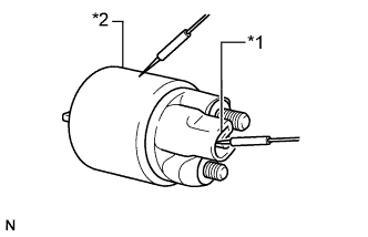
Text in Illustration *1 Terminal 50 *2 Switch Body Measure the resistance according to the value(s) in the table below.
Standard Resistance Tester Connection Connection Specified Condition Terminal 50 - Switch body Always Below 2 Ω If the result is not as specified, replace the magnet starter switch assembly.
-
-