STARTING SYSTEM INSPECTION

-
INSPECT STARTER ASSEMBLY (for 1.6 kW Type)
CAUTION:
As a large electric current passes through the cable during this inspection, a thick cable must be used. If not, the cable may become hot and cause injury.
Note
The following tests must each be performed within 3 to 5 seconds to prevent the coil from burning out.
-
Perform pull-in test.
-
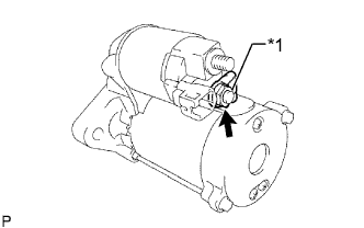
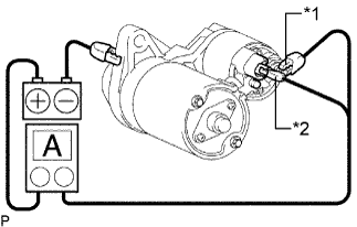
Text in Illustration *1 Terminal C Remove the nut, disconnect the field coil lead wire from terminal C.
-
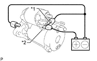
Text in Illustration *1 Terminal C *2 Terminal 50 Connect the battery to the magnetic switch as shown in the illustration. Check that the clutch pinion gear is extended.
-
-
Perform holding test.
-
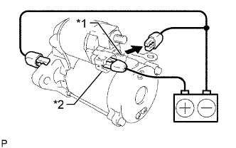
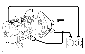
Text in Illustration *1 Terminal C *2 Terminal 50 Disconnect the negative (-) terminal lead from terminal C with the condition specified in the pull-in test above being maintained.
-
-
Check the return operation.
-
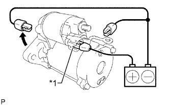
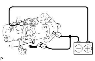
Text in Illustration *1 Terminal 50 Disconnect the negative (-) terminal lead from the starter body. Check that the clutch pinion gear returns inward.
-
-
Perform operation test without load.
-
Connect the field coil lead wire to terminal C.
- Torque:
- 10 N*m { 102 kgf*cm, 7.4 ft.*lbf }
-
-
Mount the starter in a vise between aluminum plates.
-
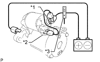
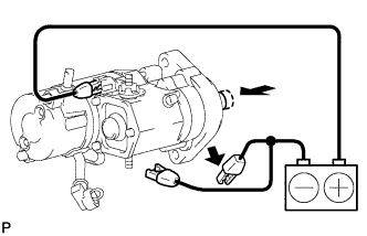
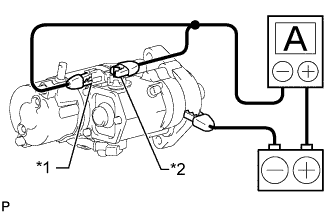
Text in Illustration *1 Terminal 30 *2 Terminal 50 *3 Ammeter Connect the battery and ammeter to the starter as shown in the illustration.
-
Check that the ammeter indicates the specified current.
Specified current 90 A or less at 11.5 V
-
-
INSPECT STARTER ASSEMBLY (for 1.7 kW Type)
CAUTION:
As a large electric current passes through the cable during this inspection, a thick cable must be used. If not, the cable may become hot and cause injury.
Note
The following tests must each be performed within 3 to 5 seconds to prevent the coil from burning out.
-
Perform pull-in test.
-
Remove the nut, and then disconnect the lead wire from terminal C.
-
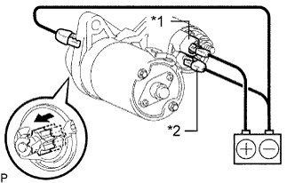
Text in Illustration *1 Terminal 50 *2 Terminal C Connect the battery to the magnet starter switch as shown in the illustration. Then check that the clutch pinion gear move outward. If the clutch pinion gear does not move, replace the magnet starter switch.
-
-
Perform holding test.
-
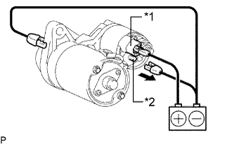
Text in Illustration *1 Terminal 50 *2 Terminal C When the battery is connected as above with the clutch pinion gear out, disconnect the negative (-) lead from terminal C. Check that the pinion gear returns out.
If the clutch pinion gear returns inward, replace the magnet starter switch.
-
-
Inspect clutch pinion gear return.
-
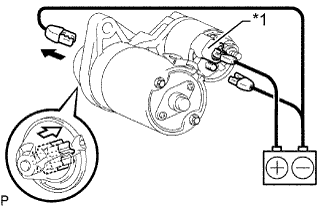
Text in Illustration *1 Terminal 50 Disconnect the negative (-) lead from the starter body. Check that the clutch pinion gear returns inward.
If the clutch pinion gear does not return inward, replace the magnet starter switch.
-
-
Perform operation test without load.
-
Connect the lead wire to terminal C.
- Torque:
- 8.0 N*m { 82 kgf*cm, 71 in.*lbf }
-
Mount the starter in a vise between aluminum plates.
-
Text in Illustration *1 Terminal 30 *2 Terminal 50 Connect the battery and an ammeter to the starter as shown in the illustration.
-
Check that the starter rotates smoothly and steadily while the pinion gear is moving outward. Then measure the current.
Standard current 90 A or less at 10.9 V If the result is not as specified, replace the starter assembly.
-
-
-
INSPECT STARTER ASSEMBLY (for 2.0 kW Type)
CAUTION:
As a large electric current passes through the cable during this inspection, a thick cable must be used. If not, the cable may become hot and cause injury.
Note
The following tests must each be performed within 3 to 5 seconds to prevent the coil from burning out.
-
Mount the starter in a vise between aluminum plates.
-
Perform pull-in test.
-
Remove the nut, and then disconnect the lead wire from terminal C.
-
Text in Illustration *1 Terminal 50 *2 Terminal C Connect the battery to the magnet starter switch as shown in the illustration. Check that the clutch pinion gear extends.
If the clutch pinion gear does not move, inspect the magnet starter switch assembly. If the magnet starter switch assembly is not as specified, replace it.
-
-
Text in Illustration *1 Terminal C Perform holding test.
-
Disconnect the negative (-) terminal lead from terminal C with the condition specified in the pull-in test above being maintained. Check that the pinion gear remains extended.
If the clutch pinion gear returns inward, inspect the magnet starter switch assembly. If the magnet starter switch assembly is not as specified, replace it.
-
-
Inspect the clutch pinion gear return.
-
Disconnect the negative (-) terminal lead from the starter body. Check that the clutch pinion gear returns inward.
If the clutch pinion gear does not return inward, inspect the magnet starter switch assembly. If the magnet starter switch assembly is not as specified, replace it.
-
-
Perform operation test without load.
-
Connect the lead wire to terminal C.
- Torque:
- 5.9 N*m { 60 kgf*cm, 52 in.*lbf }
-
Text in Illustration *1 Terminal 50 *2 Terminal 30 Connect the battery and an ammeter to the starter as shown in the illustration.
-
Check that the starter rotates smoothly and steadily while the pinion gear is extended. Then measure the current.
Specified Current 100 A or less at 11.5 V If the result is not as specified, inspect the starter assembly.
Tech Tips
Inspect the starter brush holder assembly, starter yoke assembly and starter armature assembly. If there is a malfunction, replace the part and perform this test again.
-
-