STARTER INSPECTION

-
INSPECT STARTER ARMATURE ASSEMBLY
-
Check the surface of the commutator for dirt and burns.
If the surface is dirty or burnt, correct it with sandpaper (No. 400) or a lathe.
If necessary, replace the starter armature assembly.
-
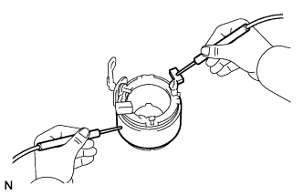
Inspect the commutator for an open circuit.
-
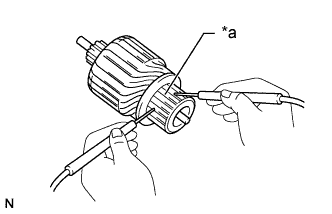
Text in Illustration *a Segment Measure the resistance according to the value(s) in the table below.
Standard Resistance Tester Connection Condition Specified Condition Segment - Segment Always Below 1 Ω If the result is not as specified, replace the starter armature assembly.
-
-
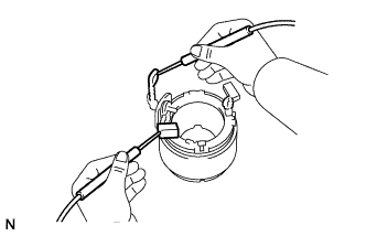
Inspect the commutator for a short circuit.
-
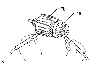
Text in Illustration *a Segment *b Coil Core Measure the resistance according to the value(s) in the table below.
Standard Resistance Tester Connection Condition Specified Condition Coil core - Segment Always 10 kΩ or higher If the result is not as specified, replace the starter armature assembly.
-
-
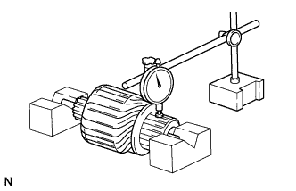
Check the commutator circle runout.
-
Place the armature shaft on V-blocks.
-
Using a dial indicator, measure the circle runout.
Maximum circle runout 0.05 mm (0.00197 in.) If the circle runout is more than the maximum, replace the starter armature assembly.
-
-
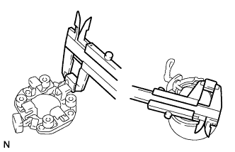
Check the commutator diameter.
-
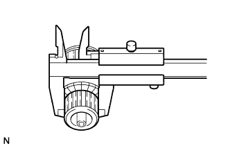
Using a vernier caliper, measure the commutator diameter.
Standard diameter 28 mm (1.10 in.) Minimum diameter 27 mm (1.06 in.) If the diameter is less than the minimum, replace the starter armature assembly.
-
-
Check the undercut depth.
-
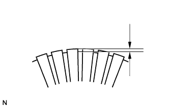
Using a vernier caliper, measure the undercut depth of the commutator.
Standard depth 0.6 mm (0.0236 in.) Minimum depth 0.2 mm (0.00787 in.) If the undercut depth is less than the minimum, replace the starter armature assembly.
-
-
-
INSPECT STARTER YOKE ASSEMBLY
-
Inspect for an open circuit.
-
Measure the resistance according to the value(s) in the table below.
Standard Resistance Tester Connection Condition Specified Condition Lead wire - Field coil brush lead Always Below 1 Ω If the result is not as specified, replace the starter yoke assembly.
-
-
Inspect for a short circuit.
-
Measure the resistance according to the value(s) in the table below.
Standard Resistance Tester Connection Condition Specified Condition Starter yoke body - Field coil brush lead Always 10 kΩ or higher If the result is not as specified, replace the starter yoke assembly.
-
-
-
INSPECT BRUSH LENGTH
-
Inspect the brush length.
-
Using a vernier caliper, measure the brush length.
Standard brush length 14.0 mm (0.551 in.) Minimum brush length 9.0 mm (0.354 in.) If the length is less than the minimum, replace the starter brush holder assembly and starter yoke assembly.
-
-
-
INSPECT STARTER BRUSH HOLDER ASSEMBLY
-
Inspect the brush insulation.
-
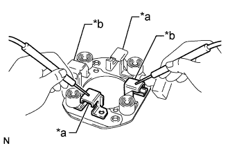
Text in Illustration *a Positive (+) brush holder *b Negative (-) brush holder Measure the resistance according to the value(s) in the table below.
Standard Resistance Tester Connection Condition Specified Condition Positive (+) brush holder - Negative (-) brush holder Always 10 kΩ or higher If the result is not as specified, replace the starter brush holder assembly.
-
-
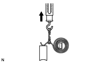
Check the brush spring load.
-
Take a pull scale reading the instant the brush spring separates from the brush.
Standard spring load 14 to 18 N (1.4 to 1.8 kgf, 3.1 to 4.0 lbf) Minimum spring load 8.8 N (0.9 kgf, 2.0 lbf) If the spring load is less than the minimum, replace the starter brush holder assembly.
-
-
-
INSPECT STARTER CENTER BEARING CLUTCH SUB-ASSEMBLY
-
Check the gear teeth on the planetary gears, and the internal gear and pinion gear of the starter center bearing clutch sub-assembly for wear or damage.
If a planetary gear or the internal gear is damaged, replace the starter center bearing clutch sub-assembly.
If the starter clutch pinion gear teeth are damaged, replace the starter center bearing clutch sub-assembly and also inspect the flywheel ring gear for wear or damage.
-
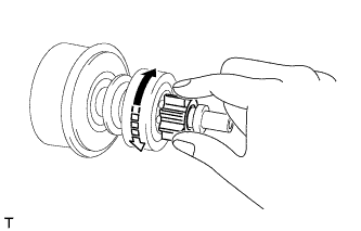
Rotate the clutch pinion gear clockwise and check that it turns freely. Try to rotate the clutch pinion gear counterclockwise and check that it locks.
Text in Illustration 
Free 
Lock If the result is not as specified, replace the starter center bearing clutch sub-assembly.
-
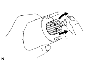
Turn the pinion gear by hand while applying inward force and check the movement of the bearing.
If resistance is felt or the bearing sticks, replace the starter center bearing clutch sub-assembly.
-
-
INSPECT MAGNET STARTER SWITCH ASSEMBLY
-
Inspect the plunger.
-
Push in the plunger and check that it returns quickly to its original position.
Note
To avoid damaging the inside of the magnet starter switch assembly, do not release the plunger quickly.
If the result is not as specified, replace the magnet starter switch assembly.
-
-
Check the pull-in coil for an open circuit.
-
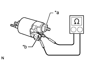
Text in Illustration *a Terminal C *b Terminal 50 Measure the resistance according to the value(s) in the table below.
Standard Resistance Tester Connection Condition Specified Condition Terminal C - Terminal 50 Always Below 1 Ω If the result is not as specified, replace the magnet starter switch assembly.
-
-
Check the holding coil for an open circuit.
-
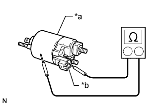
Text in Illustration *a Switch Body *b Terminal 50 Measure the resistance according to the value(s) in the table below.
Standard Resistance Tester Connection Condition Specified Condition Terminal 50 - Switch body Always Below 2 Ω If the result is not as specified, replace the magnet starter switch assembly.
-
-