STARTER (for 2.7 kW Type) INSPECTION

-
INSPECT STARTER
Note
The following tests must be performed within 3 to 5 seconds to prevent the coil from burning out.
-
Perform the pull-in test.
-
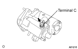
Disconnect the field coil lead wire from terminal C.
-
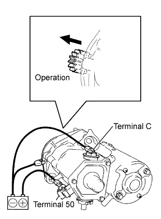
Connect the battery to the magnetic switch as shown in the illustration. Check that the clutch pinion gear is extended.
-
-
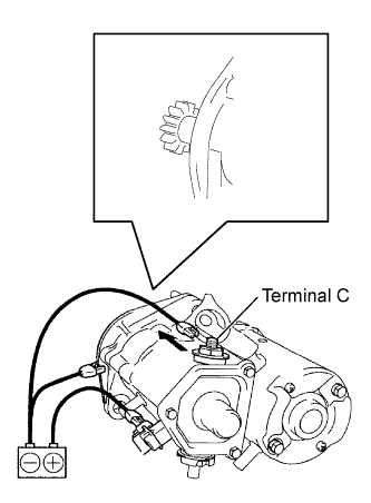
Perform the hold test.
-
Disconnect the negative (-) lead from terminal C while sustaining the above condition (a). Check that the pinion gear remains extended.
-
-
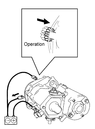
Check the return operation.
-
Disconnect the negative (-) lead from the starter body. Check that the clutch pinion gear returns inward.
-
-
Perform the operation test without any load.
-
Connect the field coil lead wire to terminal C.
- Torque:
- 24 N*m { 245 kgf*cm, 18 ft.*lbf }
-
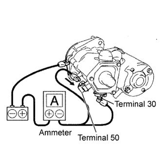
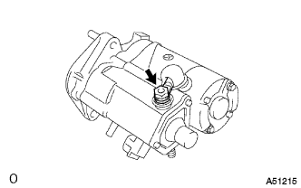
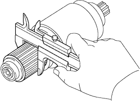
Clamp the starter in a vise.
-
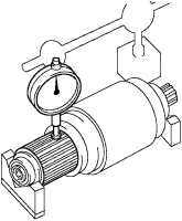
Connect the battery and ammeter to the starter as shown in the illustration.
-
Check that the ammeter indicates the specified current.
Specified current 180 A or less at 11.5 V
-
-
-
INSPECT STARTER ARMATURE ASSEMBLY
-
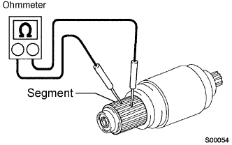
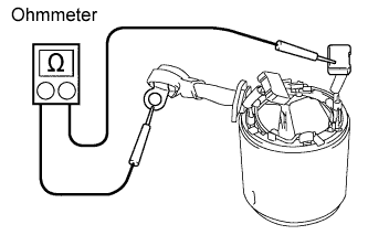
Using an ohmmeter, measure the resistance between the segments of the commutator.
Standard resistance Below 1 Ω If the results is not as specified, replace the starter armature.
-
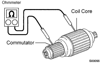
Using an ohmmeter, check the resistance between the commutator and armature coil core.
Standard resistance 10 MΩ or higher If the result is not as specified, replace the starter armature.
-
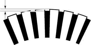
Check the commutator for circuit runout.
-
Place the commutator on V-blocks.
-
Using a dial indicator, measure the circle runout.
Maximum runout 0.05 mm (0.002 in.) If the runout is greater than the maximum, replace the starter armature.
-
-
Using vernier calipers, measure the commutator diameter.
Standard diameter 36.0 mm (1.417 in.) Minimum diameter 35.0 mm (1.378 in.) If the diameter is less than the minimum, replace the starter armature.
-
Check that the undercut portion between the segments is free of foreign objects and measure its depth.
Standard undercut depth 0.7 mm (0.028 in.) Minimum undercut depth 0.2 mm (0.008 in.) If the undercut depth is less than the minimum, correct it with a hacksaw blade.
-
Check the bearing.
-
Check that the bearing rotate smoothly.
If necessary, replace the starter armature assembly.
-
-
-
INSPECT STARTER YOKE ASSEMBLY
-
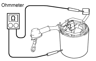
Using an ohmmeter, measure the resistance between the terminal C and brush.
Standard resistance Below 1 Ω If the result is not as specified, replace the starter yoke.
-
Using an ohmmeter, check the resistance between the starter yoke body and brushes.
Standard resistance 10 MΩ or higher If the result is not as specified, replace the starter yoke.
-
-
INSPECT STARTER BRUSH HOLDER ASSEMBLY
-
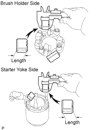
Using vernier calipers, measure the brush length.
Standard length 20.5 mm (0.807 in.) Minimum length 11.0 mm (0.433 in.) If the length is less than the minimum, replace the brush holder and starter yoke.
-
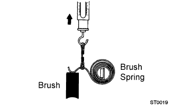
Check the pull scale reading as soon as the brush spring is separated from the brush.
Standard spring load 34.3 to 42.1 N (3.5 to 4.3 kgf, 7.7 to 9.5 lbf) Minimum spring load 18.6 N (1.9 kgf, 4.2 lbf) If the spring load is less than the minimum, replace the brush holder assembly.
-
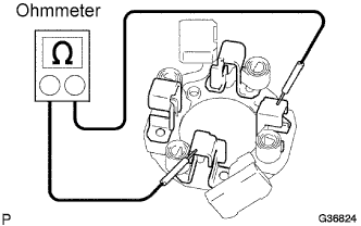
Using an ohmmeter, measure the resistance between the positive (+) and negative (-) brush holders.
Standard resistance 10 MΩ or higher If the result is not as specified, repair or replace the brush holder assembly.
-
-
INSPECT STARTER CLUTCH SUB-ASSEMBLY
-
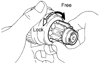
Turn the clutch pinion gear clockwise and check that it turns freely. Try to turn the clutch pinion gear counterclockwise and check that it locks.
If necessary, replace the starter clutch.
-
-
INSPECT MAGNET STARTER SWITCH ASSEMBLY
-
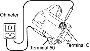
Using an ohmmeter, measure the resistance between terminals 50 and C.
Standard resistance Below 1 Ω If the result is not as specified, replace the magnet starter switch assembly.
-
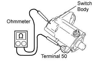
Using an ohmmeter, measure the resistance between terminal 50 and the magnet switch body.
Standard resistance Below 1 Ω If the result is not as specified, replace the magnet starter switch assembly.
-