OIL PUMP REMOVAL

-
WORK FOR PREVENTING GASOLINE FROM SPILLING OUT
-
DISCONNECT CABLE FROM NEGATIVE BATTERY TERMINAL
-
REMOVE ENGINE UNDER COVER NO.1 (w/ Engine Under Cover No.1)
-
REMOVE ENGINE UNDER COVER NO.2 (w/ Engine Under Cover No.2)
-
Remove the engine under cover No.2 together with the engine side under cover LH and engine side under cover RH (for Wide Body).
-
-
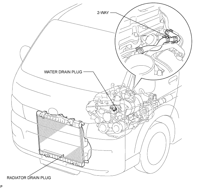
DRAIN ENGINE COOLANT
CAUTION:
Do not remove the radiator cap while the engine and radiator are still hot. Pressurized, hot engine coolant and steam may be released and cause serious burns.
-
Remove the radiator cap.
-
Loosen the radiator drain plug and a cylinder block drain plug. Then drain the coolant.
-
-
DRAIN ENGINE OIL
-
Remove the oil filler cap.
-
Remove the oil drain plug and drain the engine oil from the oil pan.
Note
Collect the oil in a disposable oil container.
-
Clean the oil pan drain plug and install it with a new gasket.
- Torque:
- 45 N*m { 459 kgf*cm, 33 ft.*lbf }
-
-
REMOVE FRONT SEAT ASSEMBLY RH
Tech Tips
Use the same procedures described for the LH side. Click here
-
REMOVE FRONT SEAT ASSEMBLY RH
Tech Tips
Use the same procedures described for the LH side. Click here
-
REMOVE FRONT DOOR SCUFF PLATE RH
-
REMOVE ENGINE SERVICE HOLE SUB COVER SUB-ASSEMBLY
-
Roll up the carpet, and remove the 5 bolts and engine service hole sub cover.
-
-
REMOVE CAM POSITION SENSOR
-
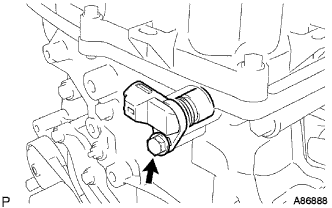
Disconnect the camshaft position sensor connector.
-
Remove the bolt and the camshaft position sensor.
-
-
REMOVE FAN & GENERATOR V BELT
-
Use the hexagon-shaped part indicated by the arrow in the illustration to move the tensioner pulley downward and decrease the tension in the drive belt. Then remove the drive belt.
Note
When removing the drive belt, do not use the idle pulley's bolt.
Tech Tips
After removing the drive belt, move the tensioner upward to the maximum amount.
-
-
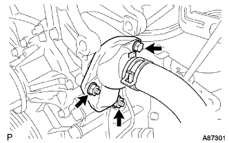
DISCONNECT RADIATOR HOSE INLET
-
Remove the clamp, and disconnect the radiator hose inlet from the engine.
-
-
DISCONNECT RADIATOR HOSE OUTLET
-
Remove the clamp, and disconnect the radiator hose outlet from the engine.
-
-
DISCONNECT FUEL VAPOR FEED HOSE ASSEMBLY
-
Disconnect the fuel vapor feed hose from the VSV.
-
-
DISCONNECT UNION TO CONNECTOR TUBE HOSE
-
Disconnect the union to connector tube hose from the intake manifold.
-
-
REMOVE INTAKE AIR CONNECTOR
-
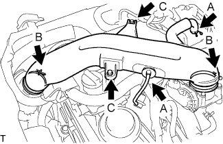
Disconnect the ventilation hose No.2 and the vacuum hose.(A)
-
Loosen the 2 hose clamp bolts.(B)
-
Remove the 2 bolts, then remove the intake air connector.(C)
-
-
DISCONNECT FUEL HOSE
-
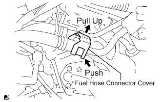
Pull the fuel hose connector cover up to release the lock. Click here
-
Disengage the fuel connector to disconnect the fuel hose. Click here
-
-
DISCONNECT FUEL HOSE NO.2
-
Remove the clamp, and disconnect the fuel hose No.2 from the delivery pipe.
-
-
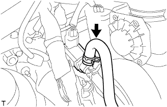
DISCONNECT VANE PUMP ASSEMBLY
-
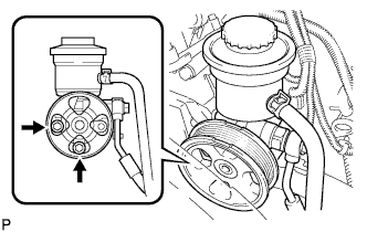
Disconnect the PS fluid pressure switch connector.
-
Remove the 2 bolts and disconnect the pump from the engine.
-
Support the vane pump securely.
-
-
REMOVE OIL LEVEL GAUGE SUB-ASSEMBLY
-
REMOVE OIL LEVEL GAUGE GUIDE
-
Remove the bolt and gauge guide.
-
-
SEPARATE COMPRESSOR AND MAGNETIC CLUTCH (w/ Air Conditioning System)
-
Disconnect the compressor connector.
-
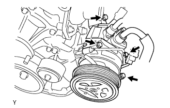
Remove the 4 bolts and disconnect the compressor from the engine.
Tech Tips
Disconnect the compressor with the low pressure hose and high pressure hose stuck by suspended from the rope.
-
Support the cooler compressor securely.
-
-
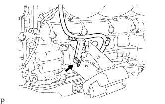
DISCONNECT ENGINE WIRE
-
Disconnect the wire harness support of the ECM.
-
Disconnect the connectors of the ECM.
-
Disconnect the clamps of the engine wire and earth cable.
-
Disconnect the +B terminal of the starter and connector from the generator.
-
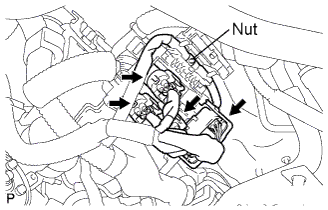
Remove the nut and disconnect the cable from the engine room J/B.
-
-
REMOVE THROTTLE WITH MOTOR BODY ASSEMBLY
-
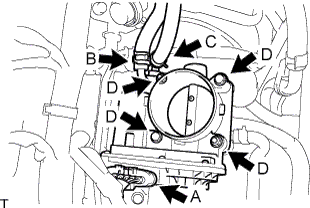
Disconnect the throttle motor connector.(A)
-
Disconnect the water by-pass hose.(B)
-
Disconnect the water by-pass hose No.2.(C)
-
Remove the 2 bolts and 2 nuts, then remove the throttle body assembly.(D)
-
Remove the gasket from the intake manifold.
-
-
REMOVE FUEL DELIVERY PIPE SUB-ASSEMBLY
Note
Be careful not to drop the injectors when removing the delivery pipe.
-
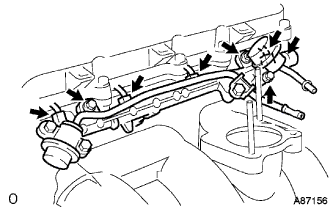
Disconnect the fuel hoses.
-
Disconnect the 4 injector connectors.
-
Remove the 2 bolts O-ring and fuel pulsation damper assembly.
-
Remove the 2 bolts and delivery pipe together with the 4 injectors.
-
Remove the delivery pipe spacers.
-
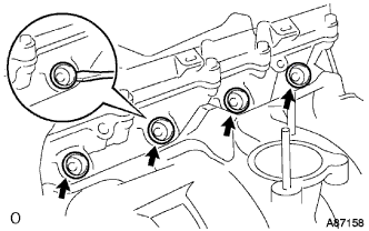
Using a screwdriver, pry out the 4 spacers from the cylinder head.
-
-
REMOVE INJECTOR ASSEMBLY
-
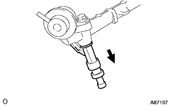
Pull out the 4 injectors from the delivery pipe.
-
Remove the O-rings from the injectors.
-
-
REMOVE INTAKE MANIFOLD
-
Disconnect the ventilation hose No.3.
-
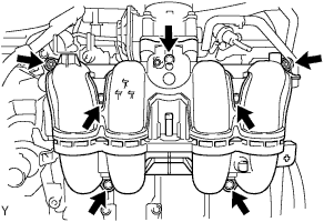
Remove the 5 bolts, 2 nuts, intake manifold and gasket.
-
-
REMOVE FAN PULLEY
-
Remove the 4 nuts, fan pulley and fan spacer.
-
-
REMOVE WATER BY-PASS PIPE NO.1
-
Remove the bolt, 2 nuts, water by-pass pipe and gasket.
-
-
REMOVE WATER INLET
-
Remove the 2 nuts, bolt, water inlet and gasket.
-
-
REMOVE THERMOSTAT
-
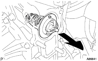
Remove the thermostat.
-
-
REMOVE GENERATOR ASSEMBLY
-
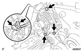
Disconnect the generator connector.
-
Remove the terminal cap.
-
Remove the nut and disconnect the wire harness from terminal B.
-
Remove the 3 bolts and generator assembly.
-
-
REMOVE COMPRESSOR MOUNTING BRACKET NO.1 (w/ Air Conditioning)
-
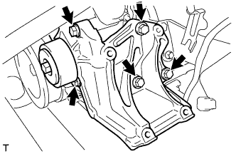
Remove the 5 bolts and compressor mounting bracket.
-
-
REMOVE IDLER PULLEY SUB-ASSEMBLY NO.1
-
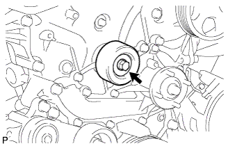
Remove the bolt, pulley plate, collar, and idler pulley sub-assembly No.1.
-
-
REMOVE V-RIBBED BELT TENSIONER ASSEMBLY
-
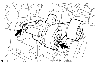
Remove the 2 bolts and belt tensioner.
-
-
REMOVE IGNITION COIL ASSEMBLY
-
Remove the bolts and ignition coil assembly.
-
-
REMOVE CYLINDER HEAD COVER SUB-ASSEMBLY
-
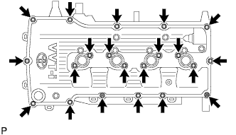
Remove the 19 bolts, 2 nuts, head cover and 2 gaskets.
-
-
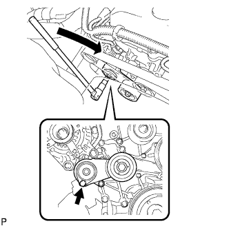
REMOVE CRANKSHAFT POSITION SENSOR
-
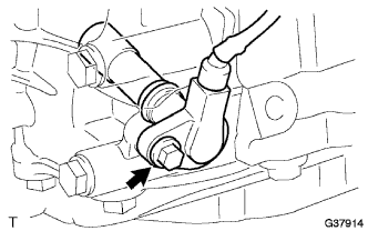
Remove the bolt and crank position sensor.
-
-
REMOVE CRANKSHAFT PULLEY
-
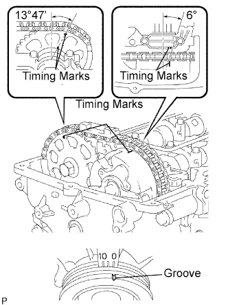
Turn the crankshaft pulley, and align its groove with timing mark 0 of the timing chain cover.
-
Check that the timing marks of the camshaft timing gear and sprocket are aligned with the timing marks of the bearing cap No.1, as shown in the illustration.
-
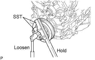
Using SST, loosen the crankshaft pulley bolt.
- SST
- 09213-54015 ( 91651-60855 )
- 09330-00021
-
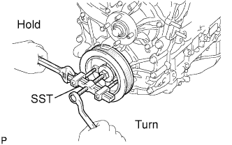
Using SST, remove the crankshaft pulley bolt and crankshaft pulley.
- SST
- 09950-50013 ( 09951-05010, 09952-05010, 09953-05010, 09954-05021 )
-
-
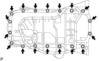
REMOVE OIL PAN SUB-ASSEMBLY NO.2
-
Remove the drain plug and gasket.
-
Remove the 18 bolts and 2 nuts.
-
Insert the blade of an oil pan seal cutter between the oil pans. Cut through the applied sealer and remove the oil pan sub-assembly No.2.
Note
Do not damage the contact surfaces of the oil pans.
-
-
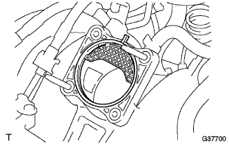
REMOVE OIL STRAINER SUB-ASSEMBLY
-
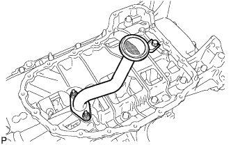
Remove the bolt, 2 nuts, oil strainer and gasket.
-
-
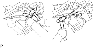
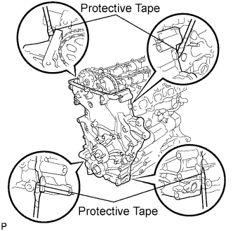
REMOVE OIL PAN SUB-ASSEMBLY
-
Remove the 16 bolts and 2 nuts.
-
Remove the oil pan by prying between the oil pan and cylinder block with a screwdriver.
Note
Do not damage the contact surfaces of the cylinder block and oil pan.
Tech Tips
Tape the screwdriver tip before use.
-
Remove the O-ring.
-
-
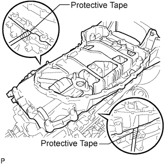
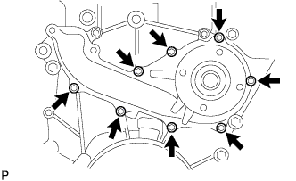
REMOVE TIMING CHAIN OR BELT COVER SUB-ASSEMBLY
-
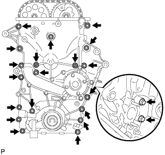
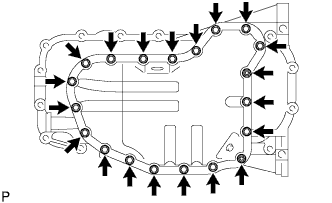
Remove the 19 bolts and 2 nuts shown in the illustration (w/o air conditioning).
-
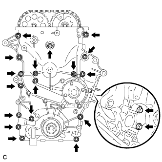
Remove the 17 bolts and 2 nuts shown in the illustration (w/ air conditioning).
-
Remove the timing chain cover by prying between the timing chain cover and cylinder head or cylinder block with a screwdriver.
Tech Tips
Tape the screwdriver tip before use.
Note
Do not damage the contact surfaces of the cylinder head, cylinder block and timing chain cover.
-
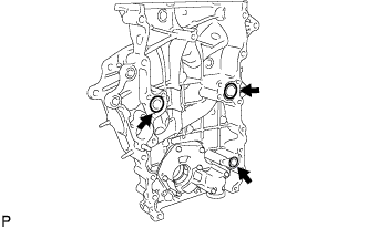
Remove the 3 O-rings.
-
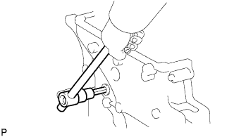
Using a 10 mm socket hexagon wrench, remove the timing chain cover plug.
-
-
REMOVE WATER PUMP ASSEMBLY
-
Remove the 8 bolts, water pump and gasket.
-
-
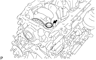
REMOVE TIMING GEAR CASE OR TIMING CHAIN CASE OIL SEAL
-
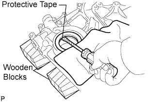
Using a screwdriver with its tip taped, pry out the oil seal.
Tech Tips
Tape the screwdriver tip before use.
-
-
REMOVE OIL PUMP RELIEF VALVE
-
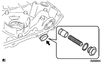
Using a 27 mm socket wrench, remove the plug and gasket.
-
Remove the valve spring and relief valve.
-