OIL PUMP INSTALLATION

-
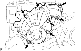
INSTALL TIMING GEAR CASE ASSEMBLY
-
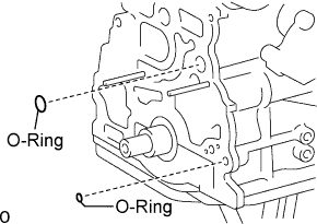
Install 2 new O-rings to the cylinder block grooves.
-
Install the stud bolt.
- Torque:
- 8.0 N*m { 82 kgf*cm, 71 in.*lbf }
-
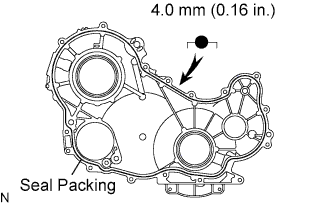
Remove any old packing (FIPG) material.
-
Install the oil pump rotor to the timing gear case.
-
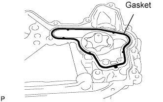
Install a new gasket to the groove of the timing gear case.
-
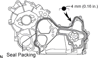
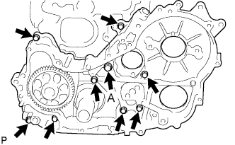
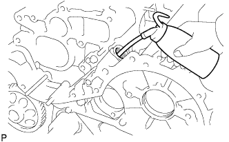
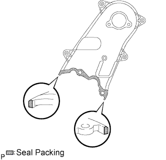
Apply seal packing to the timing gear case as shown in the illustration.
Seal packing Toyota Genuine Seal Packing Black, Three Bond 1207B or equivalent Seal width 4 mm (0.16 in.) Note
After applying FIPG, install the timing gear case assembly within 3 minutes and then tighten its bolts within 15 minutes.
-
Install the timing gear case with the union bolt and 8 bolts.
- Torque:
- 16 N*m { 163 kgf*cm, 12 ft.*lbf }
- 13 N*m { 133 kgf*cm, 10 ft.*lbf }
-
Remove the screw plug.
-
Pour approximately 50 cc (1.7 fl.oz) of engine oil into the oil pump.
-
Reinstall a new gasket and the screw plug.
- Torque:
- 42 N*m { 423 kgf*cm, 31 ft.*lbf }
-
-
INSTALL OIL STRAINER SUB-ASSEMBLY
-
Install a new gasket and the oil strainer with the 2 bolts and 2 nuts.
- Torque:
- 8.0 N*m { 82 kgf*cm, 71 in.*lbf }
-
-
INSTALL OIL PAN SUB-ASSEMBLY
-
Remove any old packing (FIPG) material.
-
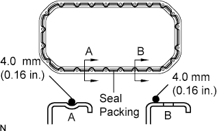
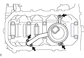
Apply seal packing to the oil pan as shown in the illustration.
Seal packing Toyota Genuine Seal Packing Black, Three Bond 1207B or equivalent Seal width 4.0 mm (0.16 in.) Note
Install the oil pan assembly within 3 minutes and tighten its bolts within 15 minutes after applying FIPG is competed.
-
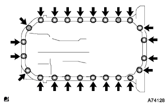
Install the oil pan with the 22 bolts and 2 nuts.
- Torque:
- 16 N*m { 163 kgf*cm, 12 ft.*lbf }
-
Install a new gasket and the drain plug.
- Torque:
- 34 N*m { 347 kgf*cm, 25 ft.*lbf }
-
-
INSTALL SUPPLY PUMP GEAR
-
Install the supply pump with the 2 nuts.
- Torque:
- 21 N*m { 214 kgf*cm, 15 ft.*lbf }
-
Temporarily install the O-ring and supply pump gear with the nut.
Tech Tips
Fit the key (protrusion) of the supply pump to the key slot of the supply pump gear.
-
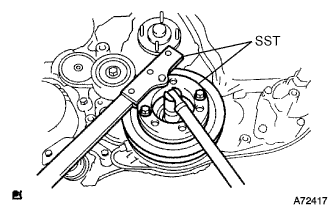
Using SST, tighten the nut.
- SST
- 09960-10010 ( 09962-01000, 09963-01000 )
- Torque:
- 64 N*m { 653 kgf*cm, 47 ft.*lbf }
-
-
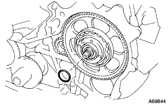
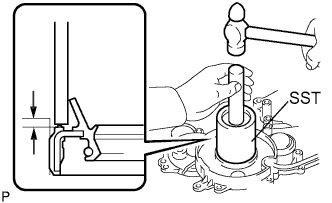
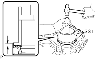
INSTALL CRANKSHAFT TIMING GEAR
-
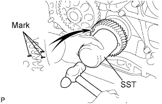
Face the crankshaft timing gear with timing mark 1 facing forward.
-
Align the set key on the crankshaft with the key groove of the crankshaft timing gear.
-
Using SST and a hammer, tap in the timing gear.
- SST
- 09223-00010
-
-
INSTALL IDLE GEAR SHAFT NO.1
-
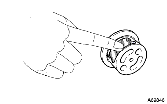
Coat the idle gear shaft No.1 with engine oil as shown in the illustration.
-
Install the gear shaft.
-
-
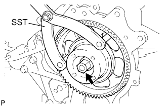
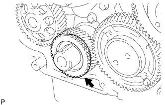
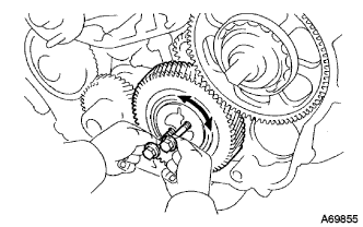
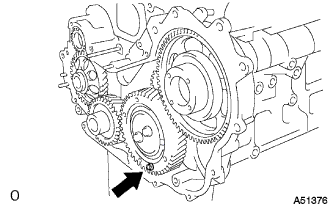
INSTALL IDLE GEAR NO.1
-
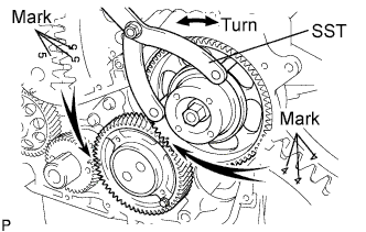
Align the "5" timing marks of the idle gear and crankshaft timing gear.
-
Using SST, turn the supply pump gear, and align the "4" timing marks of the idle gear and supply pump gear, and mesh the gears.
- SST
- 09960-10010 ( 09962-01000, 09963-00600 )
-
-
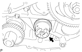
INSTALL CRANKSHAFT POSITION SENSOR PLATE NO.1
-
Align the set key with the key groove of the sensor plate.
-
Install the sensor plate with the cup side facing outward.
-
-
INSTALL IDLE GEAR THRUST PLATE
-
Face the thrust plate with the protrusion facing outward.
-
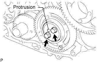
Align the bolt holes, and install the thrust plate with the 2 bolts.
- Torque:
- 50 N*m { 510 kgf*cm, 37 ft.*lbf }
-
-
INSTALL TIMING CHAIN OR BELT COVER OIL SEAL
-
Using SST and a hammer, tap in a new oil seal until its surface is flush with the timing gear cover edge.
- SST
- 09649-17010
- 09950-70010 ( 09951-07100 )
Oil seal depth from the flat-end surface 0 to -0.5 mm (0 to -0.020 in.) -
Apply MP grease to the oil seal lip.
Note
Keep the lip clean. Prevent dirt and dust from adhering to that area.
-
-
INSTALL TIMING GEAR CASE OR TIMING CHAIN CASE OIL SEAL
-
Using SST and a hammer, tap in a new oil seal until its surface is flush with the timing gear cover edge.
- SST
- 09608-32010
- 09950-70010 ( 09951-07100 )
Oil seal depth from the flat-end surface 0 to -0.5 mm (0 to -0.020 in.) -
Apply MP grease to the oil seal lip.
Note
Keep the lip clean. Prevent dirt and dust from adhering to that area.
-
-
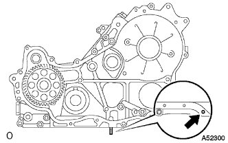
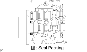
INSTALL TIMING GEAR CASE
-
Remove the service bolt.
-
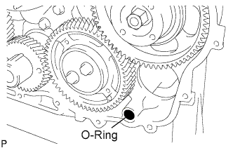
Install a new O-ring to the timing gear case assembly.
-
Apply seal packing to the timing gear case as shown in the illustration.
Seal packing Toyota Genuine Seal Packing Black, Three Bond 1207B or equivalent Seal width 4.0 mm (0.16 in.) Note
Install the timing gear case within 3 minutes and tighten its bolts within 15 minutes after applying FIPG is competed.
-
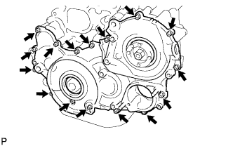
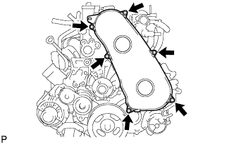
Install the timing gear case with the 14 bolts and 2 nuts.
- Torque:
- 13 N*m { 133 kgf*cm, 10 ft.*lbf }
-
-
INSTALL WATER PUMP ASSEMBLY
-
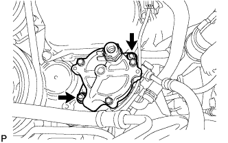
Install a new gasket and the water pump with the 5 bolts and 2 nuts.
- Torque:
- 13 N*m { 133 kgf*cm, 10 ft.*lbf }
-
-
INSTALL TIMING BELT COVER NO.2
-
Apply seal packing to the timing gear cover as shown in the illustration.
Seal packing Toyota Genuine Seal Packing Black, Three Bond 1207B or equivalent Note
Install the timing belt No. 2 cover within 3 minutes and tighten its bolts and nut within 15 minutes after applying FIPG is competed.
-
Install the timing belt No. 2 cover with the 4 bolts and nut.
- Torque:
- 10 N*m { 102 kgf*cm, 7 ft.*lbf }
-
-
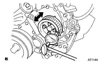
INSTALL CAMSHAFT TIMING PULLEY
-
Install the set key to the key groove of the camshaft.
-
Align the set key with the key groove of the timing pulley.
-
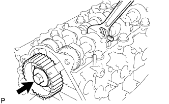
Hold the hexagon portion of the camshaft, and install the timing pulley with the bolt.
- Torque:
- 98 N*m { 1,000 kgf*cm, 72 ft.*lbf }
-
-
INSTALL CYLINDER HEAD COVER SUB-ASSEMBLY
-
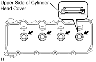
Install 4 new No. 3 cylinder head cover gaskets to the cylinder head cover as shown in the illustration.
Note
-
Do not install the gaskets at an angle.
-
Keep the lip of the gasket free from foreign materials.
-
-
Install a new cylinder head cover gasket to the cylinder head cover.
-
Apply seal packing to the cylinder head as shown in the illustration.
Seal packing Toyota Genuine Seal Packing Black, Three Bond 1207B or equivalent Note
After applying the seal packing, parts must be assembled within 3 minutes, and then tighten them within 15 minutes.
-
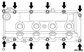
Install the cylinder head cover with 10 bolts and 2 nuts. Uniformly tighten the bolts and nuts in several steps.
- Torque:
- 9.0 N*m { 92 kgf*cm, 80 in.*lbf }
-
-
INSTALL NOZZLE HOLDER SEAL
-
Install 4 new holder seals.
-
-
INSTALL OIL FILLER CAP SUB-ASSEMBLY
-
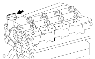
Install the oil filler cap.
-
-
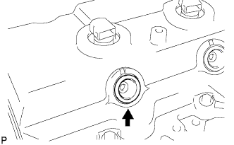
INSTALL ENGINE OIL LEVEL SENSOR
-
Set a new gasket, and then install the engine oil level sensor with the 4 bolts.
- Torque:
- 7.0 N*m { 71 kgf*cm, 52 in.*lbf }
-
-
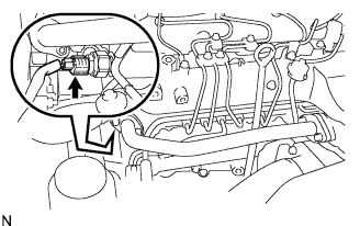
INSTALL CRANKSHAFT POSITION SENSOR
-
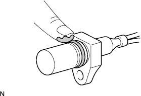
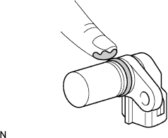
Apply a light coat of engine oil to the O-ring of the crankshaft position sensor.
-
Install the crankshaft position sensor with the bolt.
- Torque:
- 8.5 N*m { 87 kgf*cm, 75 in.*lbf }
Note
Be careful that the O-ring is not cracked or jammed when installing the crankshaft position sensor.
-
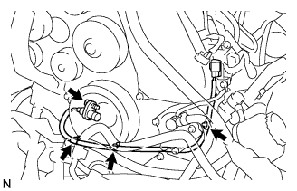
Connect the 3 wire harness clamps.
-
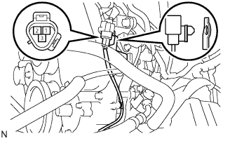
Connect the crankshaft position sensor connector to the vacuum pipe No.1.
-
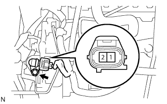
Connect the crankshaft position sensor connector.
-
-
INSTALL CAMSHAFT POSITION SENSOR
-
Apply a light coat of engine oil to the O-ring of the camshaft position sensor.
-
Install the camshaft position sensor with the bolt.
- Torque:
- 8.5 N*m { 87 kgf*cm, 75 in.*lbf }
Note
Be careful that the O-ring is not cracked or jammed when installing the camshaft position sensor.
-
Connect the camshaft position sensor connector.
-
-
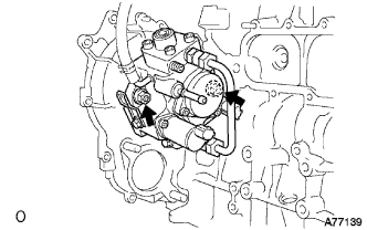
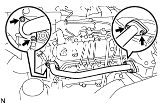
INSTALL VACUUM PUMP ASSEMBLY
-
Apply the engine oil to the 2 new O-rings.
-
Install the 2 O-rings to the vacuum pump assembly.
-
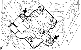
Install the vacuum pump assembly to the engine with the 2 nuts.
- Torque:
- 21 N*m { 210 kgf*cm, 15 ft.*lbf }
Note
-
Do not drop the vacuum pump packing.
-
Make sure that the vacuum pump assembly is securely installed.
-

Install the vacuum pump union and the 2 new gaskets with the union bolt.
- Torque:
- 14 N*m { 140 kgf*cm, 10 ft.*lbf }
Note
Check that the stopper of the vacuum pump union is securely holding on the vacuum pump assembly.
-
Connect the 2 hoses with the clip to the vacuum pump.
Note
Set the vacuum hose so the white marking facing upward.
-
-
INSTALL CRANKSHAFT PULLEY
-
Tighten the bolt holding the crankshaft pulley with SST.
- SST
- 09213-58013
- 09330-00021
- Torque:
- 365 N*m { 3,722 kgf*cm, 270 ft.*lbf }
-
-
INSTALL TIMING BELT IDLER SUB-ASSEMBLY NO.1.
-
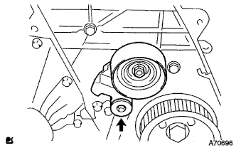
Using a 10 mm hexagon wrench, install a new washer and the timing belt idler with the bolt.
- Torque:
- 35 N*m { 357 kgf*cm, 26 ft.*lbf }
Note
Do not reuse the washer.
-
-
INSTALL V-RIBBED BELT TENSIONER ASSEMBLY
-
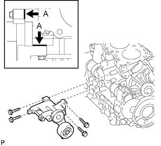
Temporarily install the V-ribbed belt tensioner with the 4 bolts.
Tech Tips
Make sure that the V-ribbed belt tensioner is in contact with the engine block at points A shown in the illustration.
-
Tighten the V-ribbed belt tensioner with the 4 bolts.
- Torque:
- 21 N*m { 214 kgf*cm, 15 ft.*lbf }
-
-
INSTALL GENERATOR ASSEMBLY
-
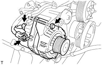
Install the generator assembly with the bolt.
- Torque:
- 62 N*m { 632 kgf*cm, 46 ft.*lbf }
-
Install the generator wire to terminal B with the nut.
- Torque:
- 9.8 N*m { 100 kgf*cm, 87 in.*lbf }
-
Install the terminal cap.
-
Connect the generator connector.
-
-
INSTALL GENERATOR BRACKET
-
Install the generator bracket with the 2 bolts.
- Torque:
- 36 N*m { 367 kgf*cm, 27 ft.*lbf }
-
-
INSTALL IDLE PULLEY ASSEMBLY
-
Install the idler pulley and washers with the bolt.
- Torque:
- 45 N*m { 459 kgf*cm, 33 ft.*lbf }
-
-
INSTALL COMPRESSOR BRACKET
-
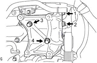
Temporarily install the compressor bracket with the 4 bolts.
Tech Tips
Make sure that the compressor bracket is in contact with the engine block.
-
Install the compressor bracket by tightening the 4 bolts as shown in the illustration.
- Torque:
- 45 N*m { 459 kgf*cm, 33 ft.*lbf }
-
-
INSTALL PUMP DRIVE SHAFT PULLEY
-
CHECK PUMP DRIVE SHAFT THRUST CLEARANCE
-
Push the pump drive shaft pulley back and forth to check a thrust clearance of the injection pump drive shaft.
Thrust clearance 0.15 to 0.55 mm (0.0059 to 0.0217 in.) Note
Make sure that the crankshaft pulley's notch is at 30 degree in the counterclockwise direction form the TDC position.
Tech Tips
If there is not thrust clearance, disassemble and reassemble the injection pump and pump drive shaft pulley.
-
-
INSTALL COMMON RAIL ASSEMBLY
-
Install the common rail assembly with the 2 bolts.
- Torque:
- 38 N*m { 387 kgf*cm, 28 ft.*lbf }
-
Connect the fuel hose to the fuel pressure limiter.
-
Connect the fuel pressure sensor connector.
-
-
INSTALL FUEL INLET PIPE SUB-ASSEMBLY
Note
-
When replacing the fuel supply pump, common rail, cylinder block, cylinder head, cylinder head gasket, or timing gear case with a new one, replace the fuel inlet pipe.
-
Be careful not to adhere dusts, dirt or any other materials onto the joint area of the fuel inlet pipe.
-
Temporarily install the fuel inlet pipe.
-
Using SST, tighten the injection pipe on the common rail side.
- SST
- 09023-12701
- Torque:
- 32 N*m { 326 kgf*cm, 24 ft.*lbf, for use with SST }
-
Using SST, tighten the injection pipe on the supply pump side.
- SST
- 09023-12701
- Torque:
- 32 N*m { 326 kgf*cm, 24 ft.*lbf, for use with SST }
-
-
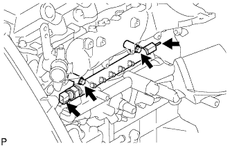
INSTALL INJECTION PIPE
- SST
- 09023-12701
Note
-
When replacing the fuel injector, common rail, or cylinder head with a new one, replace injection pipes No. 1, No. 2, No. 3, and No. 4.
-
Keep clean the joint of the injection pipe.
-
Install the injection pipes.
-
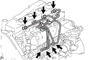
Temporarily install the 4 injection pipes.
-
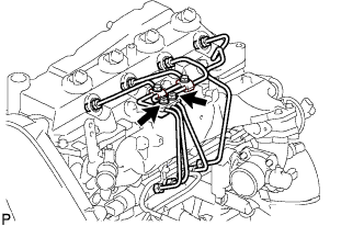
Install the injection pipe clamp No.3 in 2 nuts.
- Torque:
- 5.0 N*m { 51 kgf*cm, 44 in.*lbf }
-
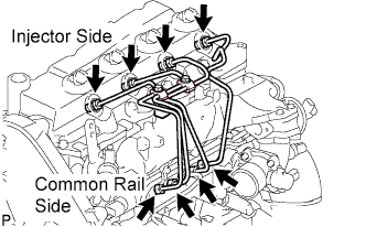
Fasten the union sequentially, from the injection pipe common rail to the injector, using SST.
- SST
- 09023-12701
- Torque:
- Use union nut wrench and torque wrench
- 32 N*m { 326 kgf*cm, 24 ft.*lbf }
-
-
INSTALL OIL LEVEL GAGE GUIDE
-
Install a new O-ring to the oil level gauge guide.
-
Apply a light coat of engine oil to the O-ring.
-
Install the oil level gauge guide with the bolt.
- Torque:
- 8.0 N*m { 82 kgf*cm, 71 in.*lbf }
-
Install the oil level gauge.
-
-
INSTALL EGR PIPE SUB-ASSEMBLY NO.1
-
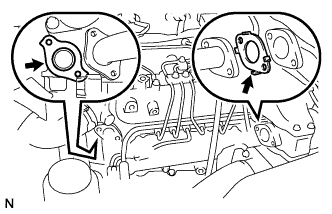
Install 2 new gaskets to the cylinder head and the EGR pipe sub-assembly No.1 as shown in the illustration.
-
Install the EGR pipe with the 2 bolts and the 2 nuts.
- Torque:
- 13 N*m { 133 kgf*cm, 10 ft.*lbf }
-
Connect the fuel pressure sensor connector.
-
-
INSTALL FAN PULLEY
-
Install the fan pulley with the 4 nuts.
- Torque:
- 23 N*m { 235 kgf*cm, 17 ft.*lbf }
-
-
PERFORM PISTON AND VALVE BREAK PREVENT WORK
-
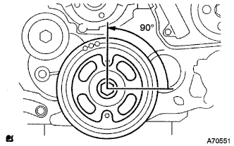
When turning the camshaft with the timing belt removed, turn the crankshaft 90° counterclockwise.
Note
When installing the timing belt, it is necessary to return the camshaft to the timing marks and then turn the crankshaft clockwise so that it aligns with the timing marks as shown in the illustration.
-
-
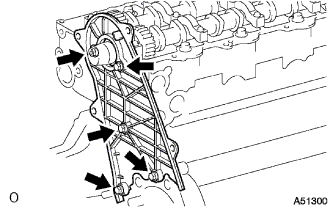
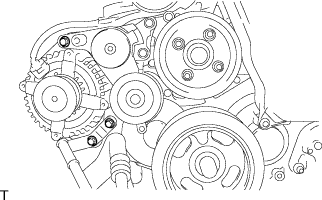
INSTALL TIMING BELT
-
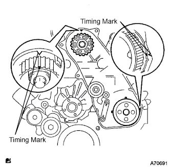
Check that the timing marks are aligned as shown in the illustration.
-
Install the timing belt to pump drive shaft pulley, camshaft timing pulley and timing belt idler No.1 in sequence.
-
Set the tensioner to the press upright.
Note
-
Do not allow the rod end to scratch and deform.
-
Press the tensioner rod in upward.
-
Protect a tip of the push rod with a rag in order to prevent damage.
-
-
Using a press, slowly apply 981 to 9,807 N (100 to 1,000 kgf, 220 to 2,205 lbf) of force to the push rod.
Note
Do not apply loads 981 to 9,807 N (100 to 1,000 kgf, 220 to 2,205 lbf) or more on the push rod.
-
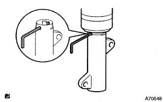
Align the holes of push rod and housing, pass a 1.27 mm hexagon wrench through the holes to keep the setting position of the push rod.
-
Temporarily install the timing belt tensioner with the 2 bolts while pushing the idler pulley toward the timing belt.
-
Tighten the 2 bolts.
- Torque:
- 13 N*m { 133 kgf*cm, 10 ft.*lbf }
Note
Uniformly tighten the 2 bolts and install the tensioner
-
Remove the 1.5 mm hexagon wrench from the tensioner.
-
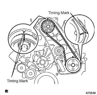
Turn the crankshaft in the clockwise direction twice, check that the timing marks are aligned as shown in the illustration.
-
-
INSTALL TIMING BELT COVER NO.1
-
Install the timing belt No.1 cover with the 6 bolts.
- Torque:
- 6.0 N*m { 61 kgf*cm, 53 in.*lbf }
-
Install the wire harness clamp.
-
-
INSTALL VANE PUMP ASSEMBLY
-
Install a new vane pump O-ring to the vane pump assembly.
-
Install the vane pump assembly with the 2 nuts.
- Torque:
- 39 N*m { 398 kgf*cm, 29 ft.*lbf }
Note
Make sure that the vane pump O-ring is not caught between other parts.
-
-
INSTALL ENGINE ASSEMBLY