ENGINE OIL COOLER REMOVAL

-
DISCONNECT CABLE FROM NEGATIVE BATTERY TERMINAL
-
DRAIN ENGINE COOLANT
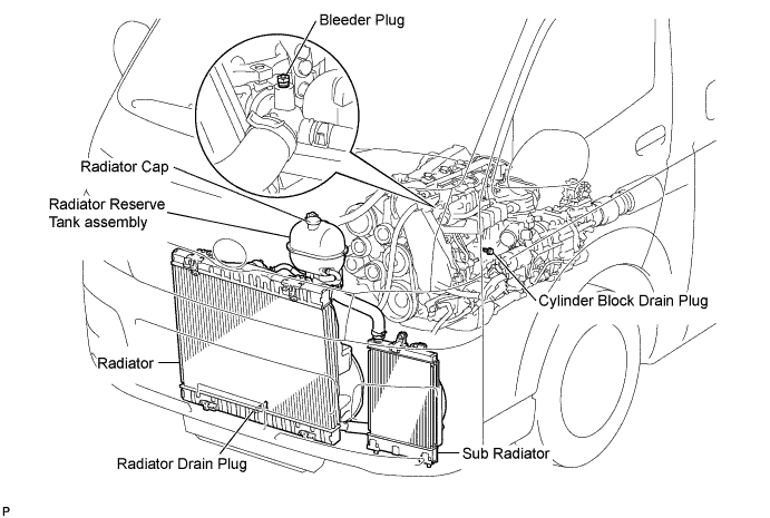
CAUTION:
To avoid the danger of being burned, do not remove the radiator reserve tank cap while the engine and radiator are still hot. Thermal expansion will cause hot engine coolant and steam to blow out from the radiator.
-
Loosen the radiator drain plug (on the radiator).
-
Remove the radiator cap.
-
Loosen the engine drain plug (on the engine oil cooler cover), and drain the coolant.
-
Tighten the engine drain plug (on the radiator).
-
Tighten the engine drain plug (on the engine oil cooler cover).
- Torque:
- 8.0 N*m { 82 kgf*cm, 71 in.*lbf }
-
-
DRAIN ENGINE OIL
-
Remove the oil filler cap.
-
Remove the drain plug from the oil pan and drain the engine oil into a container.
-
Clean the drain plug.
-
Install the drain plug with a new gasket.
- Torque:
- 34 N*m { 347 kgf*cm, 25 ft.*lbf }
-
-
REMOVE FRONT DOOR SCUFF PLATE RH
-
REMOVE FRONT SEAT ASSEMBLY RH
-

Move the front seat assembly fully forward.
-
Remove the 2 bolts on the rear side of the seat.
-
Move the front seat assembly to the rearmost position.
-
Remove the 2 bolts on the front side of the seat.
-
Move the front seat assembly to the center of the seat slide rail. Set the seatback in the upright position.
-
Disconnect the front seat inner belt assembly connector.
-
Remove the front seat assembly.
-
-
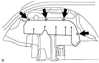
REMOVE ENGINE SERVICE HOLE SUB COVER SUB-ASSEMBLY
-
Roll up the carpet, and remove the 5 bolts and engine service hole sub cover sub-assembly.
-
-
REMOVE NO. 2 ENGINE SERVICE HOLE COVER
-
Roll up the carpet.
-
Remove the 3 bolts and No. 2 engine service hole cover.
-
-
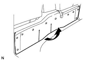
REMOVE FENDER APRON MUDGUARD SEAL LH
-
Remove the 4 clips and fender apron mudguard seal.
-
-
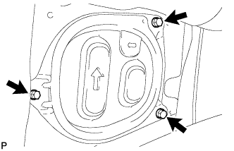
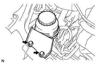
SEPARATE VANE PUMP OIL RESERVOIR ASSEMBLY
-
Remove the 2 bolts, and separate the vane pump oil reservoir assembly.
-
-
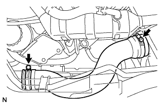
REMOVE NO. 4 AIR HOSE
-
Loosen the 2 clamps.
-
Remove the No. 4 air hose.
-
-
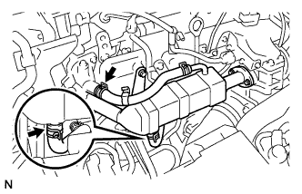
REMOVE EGR COOLER ASSEMBLY
-
Loosen the clip and disconnect the No. 4 water by-pass hose.
-
Loosen the clip and disconnect the No. 2 water by-pass hose.
-
Remove the 3 bolts and 2 nuts and remove the EGR cooler assembly.
-
-
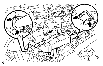
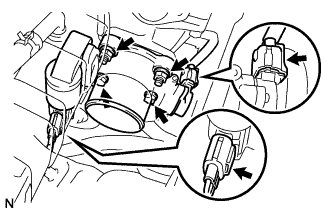
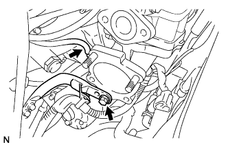
REMOVE DIESEL THROTTLE BODY ASSEMBLY
-
Disconnect the 2 throttle body connectors.
-
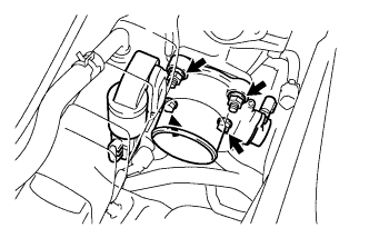
Remove the 2 bolts, 2 nuts, and the diesel throttle body assembly.
-
Remove the gasket from the intake air connector.
-
-
REMOVE ELECTRIC EGR CONTROL VALVE ASSEMBLY
-
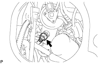
Disconnect the intake air temperature sensor connector.
-
Remove the vacuum regulating valve.
-
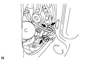
Remove the 2 vacuum hoses and the vacuum regulating valve connector.
-
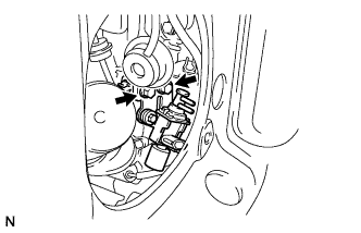
Remove the 2 bolts and the vacuum regulating valve.
-
-
Remove the electric EGR control valve with the sensor.
-
Remove the bolt, and separate the manifold stay.
-
Disconnect the vacuum hose from the intake air connector.
-
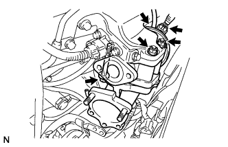
Disconnect the EGR valve position sensor connector.
-
Disconnect the vacuum hose from the electric EGR control valve.
-
Remove the bolt, 2 nuts and intake air connector assembly.
-
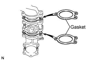
Remove the 2 gaskets and electric EGR control valve from the intake air connector.
-
-
-
REMOVE OIL LEVEL GAUGE GUIDE
-
Remove the oil level gauge.
-
Remove the bolt and oil level gauge guide.
-
-
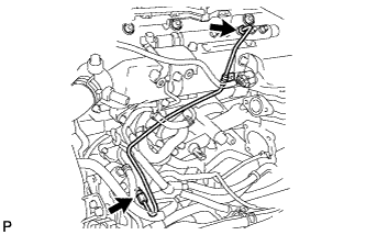
REMOVE INJECTION PIPE SUB-ASSEMBLY
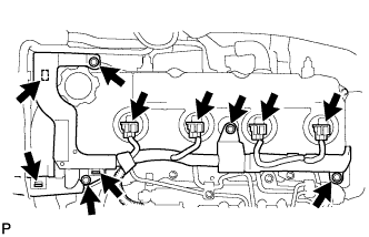
-
Disconnect the fuel injector connector and harness clamps.
-
Remove the 3 bolts.
-
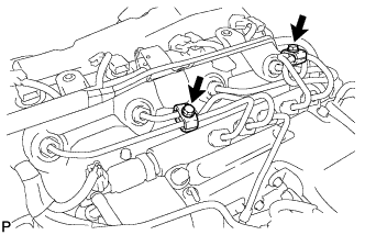
Remove the 2 bolts and remove the 2 No. 2 injection pipe clamps.
-
Using SST, remove the 4 injection pipes.
- SST
- 09023-12701
-
-
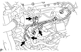
REMOVE FUEL INLET PIPE SUB-ASSEMBLY
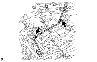
-
Remove the 2 clamp bolts.
-
Using SST, loosen the 2 union nuts and remove the fuel inlet pipe sub-assembly.
- SST
- 09023-12701
-
-
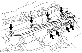
REMOVE NO.2 NOZZLE LEAKAGE PIPE ASSEMBLY
-
Disconnect the 4 fuel hoses from the No. 2 nozzle leakage pipe assembly.
-
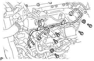
Remove the 2 union bolts, 3 bolts and remove the No. 2 nozzle leakage pipe assembly.
-
-
REMOVE FUEL COOLER
-
Slide the clip and disconnect the water by-pass hose from the oil cooler cover.
-
Remove the 2 bolts and fuel cooler.
-
-
REMOVE OIL FILTER SUB-ASSEMBLY
-
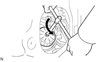
Using SST, remove the oil filter.
- SST
- 09228-07501
Tech Tips
Position the drain oil container to collect the oil from the oil filter.
-
-
REMOVE OIL COOLER COVER SUB-ASSEMBLY
-
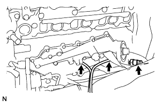
Disconnect the oil pressure switch connector.
-
Disconnect the 2 oil filter drain hoses.
-
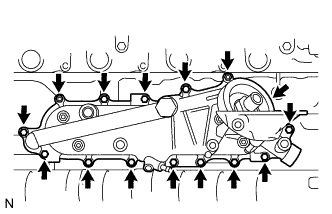
Remove the 13 bolts, 2 nuts and separate the No. 2 vacuum transmitting pipe.
-
Remove the oil cooler cover and gasket from the cylinder block.
-
-
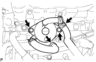
REMOVE OIL COOLER ASSEMBLY
-
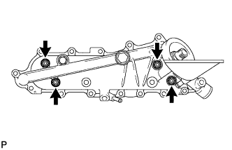
Remove the 4 nuts and remove the engine oil cooler and 2 gaskets from the oil cooler cover.
-