ENGINE OIL COOLER INSTALLATION

-
INSTALL OIL COOLER ASSEMBLY
-
Install the 2 new gaskets, and the oil cooler with the 4 nuts to the filter bracket.
- Torque:
- 16 N*m { 160 kgf*cm, 11 ft.*lbf }
-
-
INSTALL OIL FILTER BRACKET SUB-ASSEMBLY
-
Install a new gasket and oil filter bracket with the 10 bolts and 2 nuts.
- Torque:
- 30 N*m { 300 kgf*cm, 22 ft.*lbf }
-
-
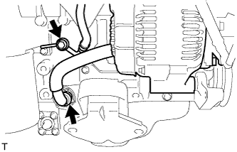
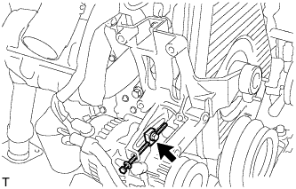
INSTALL VACUUM PUMP OIL INLET HOSE
-
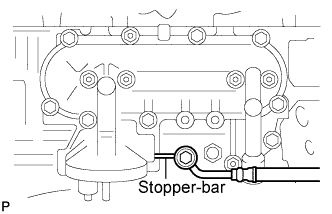
Connect the vacuum pump oil inlet hose with 2 new gaskets and the union bolt.
- Torque:
- 14 N*m { 140 kgf*cm, 10 ft.*lbf }
CAUTION:
Catch a stopper-bar of the inlet hose with the oil filter bracket.
-
-
INSTALL OIL FILTER SUB-ASSEMBLY
-
Check and clean the oil filter installation surface.
-
Apply clean engine oil to the rubber gasket of a new oil filter.
-
Instal the oil filter, and tighten it by hand until the rubber gasket contacts the installation surface.
-
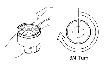
Using SST, tighten it by an additional 3/4 turn to seat the filter.
- SST
- 09228-44011
-
-
INSTALL EXHAUST MANIFOLD
-
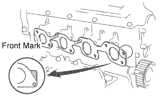
Install a new gasket to the cylinder head.
Tech Tips
Be sure to install a new gasket in the correct direction as shown in the illustration.
-
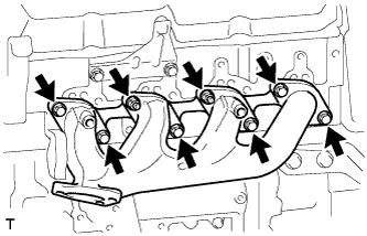
Install the exhaust manifold with the 6 bolts and 2 new nuts. Uniformly tighten the bolts and nuts in several steps.
- Torque:
- 52 N*m { 530 kgf*cm, 38 ft.*lbf }
-
-
INSTALL EXHAUST MANIFOLD HEAT INSULATOR NO.1
-
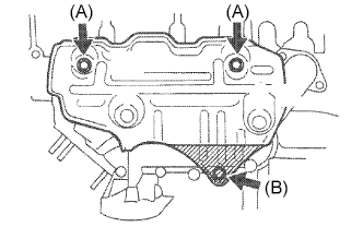
Install the heat insulator with the 3 bolts.
- Torque:
- Bolt (A)
- 18 N*m { 185 kgf*cm, 13 ft.*lbf }
- Bolt (B)
- 19 N*m { 195 kgf*cm, 14 ft.*lbf }
-
-
INSTALL EXHAUST PIPE ASSEMBLY FRONT
-
INSTALL GENERATOR W/ VACUUM PUMP ASSEMBLY
-
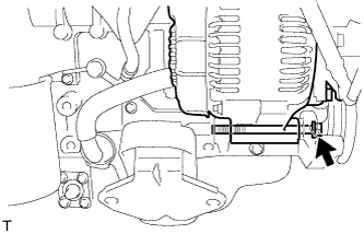
Temporarily tighten the bolt and generator w/ vacuum pump assembly.
-
Install the clip with the hose connected.
-
Install the bolt with the hose connected.
- Torque:
- 14 N*m { 140 kgf*cm, 10 ft.*lbf }
-
-
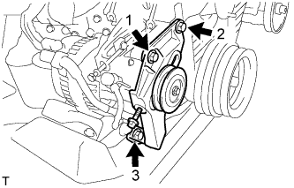
INSTALL COMPRESSOR MOUNTING BRACKET (w/ Air Conditioning)
-
Temporarily install the compressor mounting bracket with the 4 bolts.
-
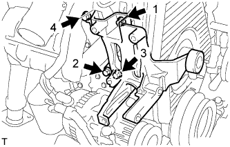
Using several steps, uniformly install and tighten the 4 bolts in the sequence shown in the illustration.
- Torque:
- 85 N*m { 870 kgf*cm, 63 ft.*lbf }
-
Temporarily tighten the bolt and spacer.
-
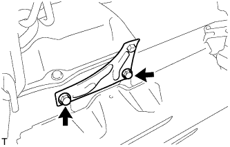
Temporarily install the compressor mounting bracket with the 3 bolts.
-
Using several steps, uniformly install and tighten the 3 bolts in the sequence shown in the illustration.
- Torque:
- 47 N*m { 475 kgf*cm, 36 ft.*lbf }
-
-
INSTALL COMPRESSOR AND MAGNETIC CLUTCH (w/ Air Conditioning System)
-
INSTALL FAN & GENERATOR V BELT (w/ Air Conditioning System)
-
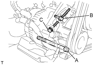
Install the V belt.
-
Tightening the bolt C, adjust the tension of the V belt.
-
Tighten the bolts A and B.
- Torque:
- Bolt A
- 75 N*m { 765 kgf*cm, 55 ft.*lbf }
- Bolt B
- 18 N*m { 185 kgf*cm, 13 ft.*lbf }
-
Check the tension of the V belt. Click here
-
-
INSTALL FAN & GENERATOR V BELT (w/o Air Conditioning)
-
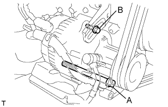
Install the V belt.
-
Using a bar, adjust the tension of the V belt.
-
Tighten the bolts A and B.
- Torque:
- Bolt A
- 75 N*m { 765 kgf*cm, 55 ft.*lbf }
- Bolt B
- 18 N*m { 185 kgf*cm, 13 ft.*lbf }
-
Check the tension of the V belt. Click here
-
-
INSTALL V (COOLER COMPRESSOR TO CRANKSHAFT PULLEY) BELT NO.1 (w/ Air Conditioning System)
-
Install the V belt.
-
Tightening the bolt B, adjust the tension of the V belt.
-
Tighten nut A.
- Torque:
- 39 N*m { 400 kgf*cm, 29 ft.*lbf }
-
Check the tension of the V belt. Click here
-
-
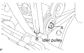
INSTALL VANE PUMP V BELT
-

Install the V belt.
-
Using a bar, adjust the tension of the V-ribbed belt.
-
Tighten the bolt A and nut B.
- Torque:
- Bolt (A)
- 48 N*m { 489 kgf*cm, 35 ft.*lbf }
- Nut (B)
- 64 N*m { 635 kgf*cm, 47 ft.*lbf }
-
Check the tension of the V belt. Click here
-
-
INSTALL OIL LEVEL GAGE GUIDE
-
Install the level gage guide with the 2 bolts.
- Torque:
- 12 N*m { 122 kgf*cm, 9 ft.*lbf }
-
-
INSTALL OIL LEVEL GAGE SUB-ASSEMBLY
-
INSTALL INTAKE AIR CONNECTOR BRACKET
-
Install the 2 bolts and intake air connector bracket.
- Torque:
- 18 N*m { 184 kgf*cm, 13 ft.*lbf }
-
-
INSTALL INTAKE AIR CONNECTOR SUB-ASSEMBLY
-
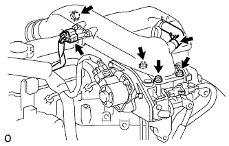
Install a new gasket and intake air connector with the bolt and 3 nuts.
- Torque:
- bolt
- 18 N*m { 184 kgf*cm, 13 ft.*lbf }
- Nut
- 12 N*m { 122 kgf*cm, 9 ft.*lbf }
-
Connect the turbo pressure sensor connector.
-
Connect the ventilation hose.
-
-
ADD ENGINE OIL
-
ADD ENGINE COOLANT
-
Fill the radiator reservoir assembly with coolant to the top of the inlet.
Standard Capacity Item Specified Condition w/o Heater 12.3 liters (13.0 US qts, 10.8 Imp. qts) w/ Front Heater 13.3 liters (14.1 US qts, 11.7 Imp. qts) w/ Front and Rear Heaters 15.3 liters (16.2 US qts, 13.5 Imp. qts) Note
Do not substitute plain water for engine coolant.
Tech Tips
-
Use of improper coolants may damage the engine cooling system.
-
Use only Toyota Super Long Life Coolant or similar high quality ethylene glycol based non-silicate, non-amine, non-nitrite, and non-borate coolant with long-life hybrid organic acid technology (coolant with long-life hybrid organic acid technology consists of a combination of low phosphates and organic acids).
-
-

Add coolant up to the B line mark in the radiator reservoir assembly and install the reservoir cap.
-
Warm up the engine until the thermostat opens.
-
While the thermostat is open, circulate the coolant for several minutes.
Tech Tips
The thermostat open timing can be confirmed by pressing the inlet radiator hose by hand, and checking when the engine coolant starts to flow inside the hose.
-
-

After the engine cools down, check that the coolant level is between the LOW and FULL level marks.
-
-
CHECK FOR ENGINE OIL LEAKS
-
CHECK FOR ENGINE COOLANT LEAKS
CAUTION:
Do not remove the radiator cap while the engine and radiator are still hot. Pressurized, hot engine coolant and steam may be released and cause serious burns.
-
Fill the radiator with coolant and attach a radiator cap tester to the radiator.
-
Warm up the engine.
-
Using a radiator cap tester, increase the pressure inside the radiator to 118 kPa (1.2 kgf/cm2, 17.1 psi), and check that the pressure does not drop.
Tech Tips
If the pressure drops, check the hoses, radiator or water pump for leaks. If no external leaks are found, check the heater core, cylinder block, and cylinder head.
-
-
INSTALL ENGINE SERVICE HOLE SUB COVER SUB-ASSEMBLY
-
Install the 5 bolts and engine service hole cover.
- Torque:
- 13 N*m { 133 kgf*cm, 10 ft.*lbf }
-
-
INSTALL FRONT DOOR SCUFF PLATE RH
-
INSTALL FRONT SEAT ASSEMBLY RH
-

Connect the front seat inner belt assembly connector and install the front seat assembly.
-
Align the front seat assembly adjuster pin with the holes in the body.
-
Move the front seat assembly to the rearmost position.
Note
Make sure that the front seat assembly is securely locked.
-
Temporarily tighten the 2 bolts on the front side of the front seat assembly.
-
Move the front seat assembly fully forward.
Note
Make sure that the front seat assembly is securely locked.
-
Temporarily tighten the 2 bolts on the rear side of the front seat assembly.
-
Move the front seat assembly to the rearmost position.
Note
Make sure that the front seat assembly is securely locked.
-
Fully tighten the 2 bolts on the front side of the front seat assembly in the order of outer and inner side.
- Torque:
- 39 N*m { 398 kgf*cm, 29 ft.*lbf }
-
Move the front seat assembly fully forward.
Note
Make sure that the front seat assembly is securely locked.
-
Fully tighten the 2 bolts on the rear side of the front seat assembly in the order of outer and inner side.
- Torque:
- 39 N*m { 398 kgf*cm, 29 ft.*lbf }
-