COOLING FAN SYSTEM ON-VEHICLE INSPECTION

-
INSPECT COOLING FAN SYSTEM
-
Put the vehicle in the following state:
-
The ignition switch is off.
-
The coolant temperature is less than 76°C (169°F).
-
The battery voltage is between 11 and 14 V.
-
The A/C switch is off.
-
-
Connect the 400 A probe of the ammeter to the M+ terminal of the cooling fan motor No.1 (No.2).
-
Turn the ignition switch to the ON position (engine off) and wait for approximately 10 seconds. Check that the fans stop.
-
Start the engine. Check that the fans stop with the engine idling.
Tech Tips
Make sure that the radiator coolant temperature is less than 76°C (169°F) and the A/C switch is off.
-
Check that the fans operate when the A/C switch is turned on (The temperature is set to MAX COOL and the magnet clutch is operating).
Tech Tips
The coolant temperature is less than 76°C (169°F).
Standard Fan motor No.1 4 to 23 A Fan motor No.2 4 to 23 A (w/ air conditioning) -
Check that the fans operate when the coolant sensor connector is disconnected.
Standard Fan motor No.1 8 to 24 A Fan motor No.2 8 to 24 A (w/ air conditioning) -
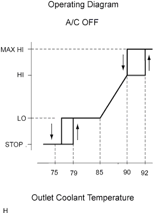
After the engine has warmed up, the fans operate as shown in the illustration.
Tech Tips
The coolant temperature at which the fans start operating is approximately 79°C (174°F).
Tech Tips
-
This system can also be checked using the intelligent tester.
-
Select the following menu items: Powertrain / Engine / Date List/ Initial Engine Coolant Temp.
-
-
-
INSPECT COOLING FAN ECU
-
Check the input voltage.
-
Disconnect the cooling fan ECU No.1(No.2) connector.
-
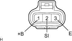
Turn the ignition switch to the ON position. Measure the voltage at the +B1 (+B2) terminal of the disconnected harness side connector.
Standard 9 to 14 V -
If the terminal voltage is not within the specification, inspect the power source system (fusible link, fuse, wire harness, relay).
-
-
Inspect the cooling fan motor.
-
Inspect the wire harness.
-
Disconnect the ECM and cooling fan ECU No.1 (No.2) connectors.
-
Check continuity and the insulation condition between the terminal RFC of the ECM and terminal SI (SI2) cooling fan ECU.
Tech Tips
If the fan does not operate, there may be a short circuit. If the fan remains operating, there may be an open circuit.
-
Inspect the ECM power source circuit and ground circuit.
-
-
Inspect the input signal and output current.
Note
Be sure to perform the inspection with the radiator coolant temperature less than 79°C (174°F).
-
Connect the 400 A probe of the ammeter to the M+ terminal of the cooling fan motor No.1 (No.2).
-
Set the intelligent tester to the oscilloscope function.
-
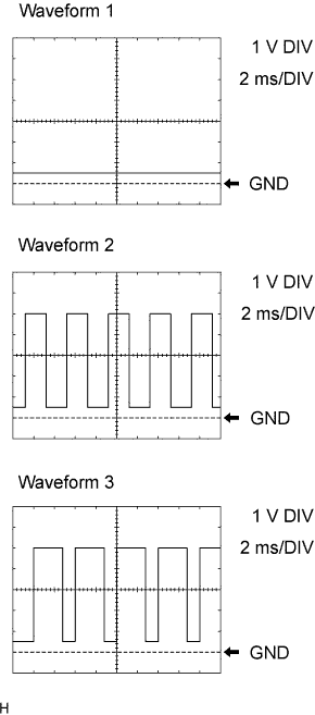
Using the intelligent tester, check waveform between terminals RFC and E1 (E2) of the ECM.
Standard Condition Input signal Output current Engine stopped
IG switch ON
Wave form 1
(Duty ratio 0 %)
(Fan stops) Engine idling
A/C OFF
Waveform 1
(0 %)
(Fan stops) Engine idling
A/C ON
Waveform 2
(40 to 70 %)
4 to 23 A
(Fan operates)
Engine idling and ECT sensor connector disconnected Waveform 3
(70 %)
8 to 24 A
(Fan operates)
Tech Tips
-
If the input signal is abnormal, there is a malfunction in the ECM or cooling fan ECU.
-
If the output current is abnormal, there is a malfunction in the cooling fan ECU or motor.
-
-
-