OIL PUMP (w/ DPF) INSTALLATION

Note
-
When replacing the injectors (including shuffling the injectors between the cylinders), common rail or cylinder head, it is necessary to replace the injection pipes with new ones.
-
When replacing the fuel supply pump, common rail, cylinder block, cylinder head, cylinder head gasket or timing gear case, it is necessary to replace the fuel inlet pipe with a new one.
-
After removing the injection pipes, clean them with a brush and compressed air.
-
INSTALL TIMING GEAR CASE ASSEMBLY
-
Remove any old seal packing (FIPG material).
-
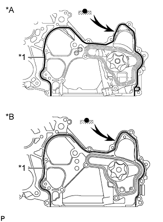
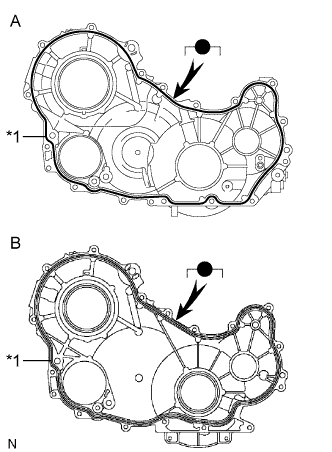
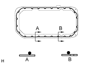
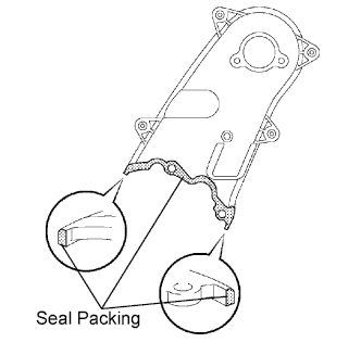
Text in Illustration *A w/ DPF *B w/o DPF *1 Seal Packing Apply seal packing to the timing gear case as shown in the illustration.
Seal packing Toyota Genuine Seal Packing Black, Three Bond 1207B or equivalent Standard seal diameter 4 mm (0.16 in.) Note
After applying seal packing, install the timing gear case assembly within 3 minutes and tighten the bolts within 15 minutes.
-
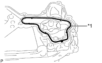
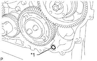
Text in Illustration *1 New Gasket Install a new gasket to the groove of the timing gear case.
-
Install 2 new O-rings.
-

Align the "2" marks of the No. 1 balanceshaft driven gear and oil pump drive gear.
-
Align the mark on the oil pump drive gear with the mark on the timing gear case.
-
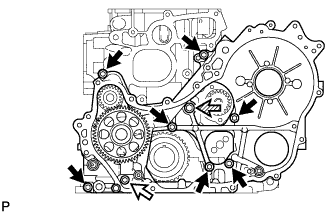
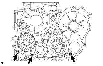
w/ DPF:
Install the timing gear case with the union bolt and 8 bolts.
- Torque:
- for bolt A
- 13 N*m { 133 kgf*cm, 10 ft.*lbf }
- for bolt B
- 10 N*m { 102 kgf*cm, 7 ft.*lbf }
- for union bolt
- 16 N*m { 163 kgf*cm, 12 ft.*lbf }
Text in Illustration 
Bolt A 
Bolt B 
Union bolt -
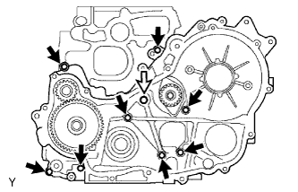
w/o DPF:
Install the timing gear case with the union bolt and 8 bolts.
- Torque:
- for bolt
- 13 N*m { 133 kgf*cm, 10 ft.*lbf }
- for union bolt
- 16 N*m { 163 kgf*cm, 12 ft.*lbf }
Text in Illustration Bolt Union bolt -
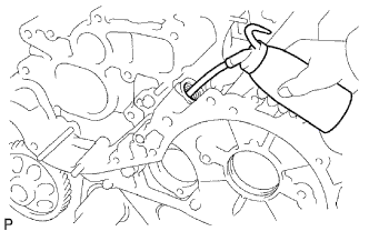
Remove the screw plug and gasket.
-
Pour approximately 50 cc (3.05 cu. in.) of engine oil into the oil pump.
-
Install a new gasket and the screw plug.
- Torque:
- 44 N*m { 449 kgf*cm, 32 ft.*lbf }
-
-
INSTALL INJECTION GEAR
-
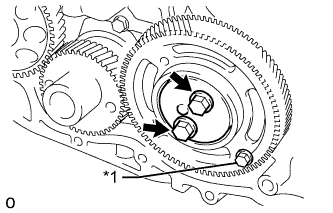
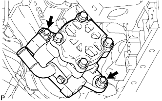
Install a new O-ring and the fuel supply pump with the 2 nuts.
- Torque:
- 21 N*m { 214 kgf*cm, 15 ft.*lbf }
-
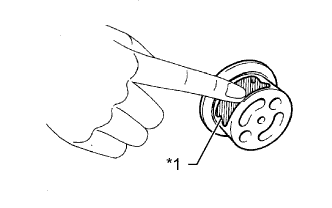
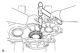
Temporarily install the injection gear with the nut.
Tech Tips
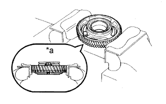
Make sure that the key slot of the injection gear fits over the key (protrusion) of the supply pump.
-
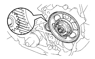
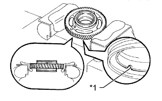
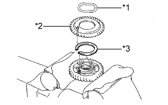
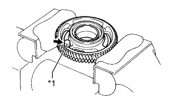
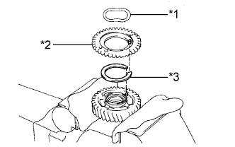
Align the "3" marks of the No. 2 balanceshaft driven gear and injection gear.
-
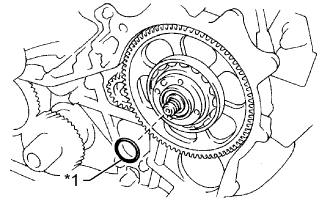
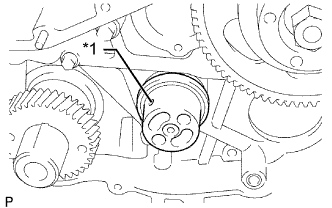
Text in Illustration *1 New O-Ring Install a new O-ring to the injection gear.
-
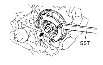
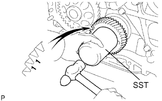
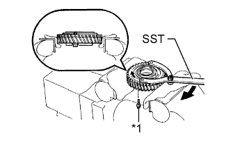
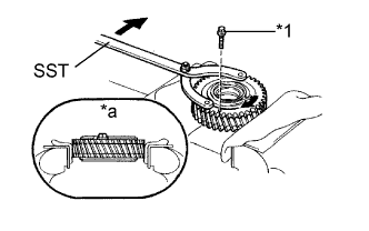
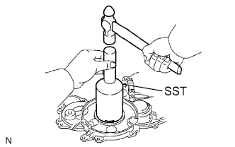
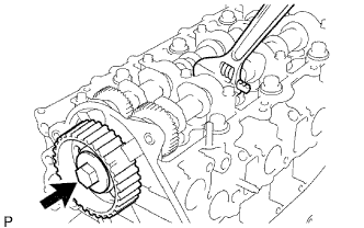
Temporarily install the injection gear set nut.
-
Using SST, tighten the nut.
- SST
- 09960-10010 ( 09962-01000, 09963-01000 )
- Torque:
- 64 N*m { 650 kgf*cm, 47 ft.*lbf }
-
-
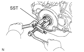
INSTALL CRANKSHAFT TIMING GEAR
-
Position the crankshaft timing gear with the "1" timing marks facing forward.
-
Align the key groove of the crankshaft timing gear with the set key on the crankshaft.
-
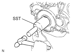
Using SST and a hammer, tap on the timing gear to install it.
- SST
- 09223-00010
-
-
INSTALL NO. 1 IDLE GEAR SHAFT
-
Text in Illustration *1 Engine Oil Apply a coat of engine oil to the No. 1 idle gear shaft.
-
Text in Illustration *1 Oil Hole Install the No. 1 gear shaft as shown in the illustration.
-
-
INSTALL NO. 1 IDLE GEAR
-
Text in Illustration *1 Cutout Mark Mount the No. 1 idle gear in a vise.
Tech Tips
Make sure the cutout mark of the idle gear faces down.
Note
Be careful not to damage the gear.
-
Text in Illustration *1 Wave Washer *2 No. 2 Idle Sub Gear *3 Idle Gear Spring Install the idle gear spring.
-
Install the No. 2 idle sub gear.
-
Install the wave washer.
Tech Tips
Fit the pins on the gears between the spring ends.
-
Using snap ring pliers, install the shaft snap ring.
-
Text in Illustration *1 Service Bolt Using SST, align the holes of the No. 1 idle gear and No. 2 idle sub gear by turning the No. 2 idle sub gear clockwise, and install a service bolt.
- SST
- 09960-10010 ( 09962-01000, 09963-00700 )
-
Remove the No. 1 idle gear from the vise and turn it upside down.
-
Text in Illustration *a Upward Mount the No. 1 idle gear and No. 2 idle sub gear in a vise.
Note
Be careful not to damage the gears.
-
Text in Illustration *1 Service Bolt Remove the service bolt.
-
Text in Illustration *1 Wave Washer *2 No. 1 Idle Sub Gear *3 Idle Gear Spring Install the idle gear spring.
-
Install the No. 1 idle sub gear.
-
Install the wave washer.
Tech Tips
Fit the pins on the gears between the spring ends.
-
Using snap ring pliers, install the snap ring.
-
Text in Illustration *1 Service Bolt *a Upward Using SST, align the holes of the No. 1 idler gear and No. 1 idle sub gear by turning the No. 1 idle sub gear clockwise, and install a service bolt.
- SST
- 09960-10010 ( 09962-01000, 09963-00600 )
-
Text in Illustration *a Turn Align the "5" timing marks of the idle gear and crankshaft timing gear.
-
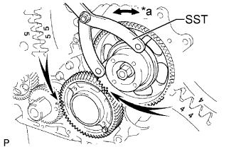
Using SST, turn the injection gear and align the "4" timing marks of the idle gear and injection gear, and then mesh the gears.
- SST
- 09960-10010 ( 09962-01000, 09963-01000 )
-
Text in Illustration *1 Service Bolt Position the thrust plate with the protrusion facing forward.
-
Align the bolt holes and install the thrust plate with the 2 bolts.
- Torque:
- 50 N*m { 510 kgf*cm, 37 ft.*lbf }
-
Remove the service bolt.
-
-
INSTALL NO. 1 CRANKSHAFT POSITION SENSOR PLATE
-
Align the key groove of the No. 1 crankshaft position sensor plate with the set key.
-
Install the No. 1 crankshaft position sensor plate with the cupped side facing outward.
Tech Tips
When replacing the No. 1 crankshaft position sensor plate, perform "Crank Time Compensation Reset" (w/DPF: Click here, w/o DPF: Click here.
-
-
INSTALL TIMING GEAR COVER OIL SEAL
Tech Tips
There are 2 methods to remove the oil seal.
-
If the timing gear cover is removed from the cylinder block:
-
Using a screwdriver and hammer, tap out the oil seal.
-
Using SST and a hammer, tap in a new oil seal until its surface is flush with the timing gear cover edge.
- SST
- 09214-76011
-
Apply MP grease to the lip of the oil seal.
-
-
If the timing gear cover is installed to the cylinder block:
-
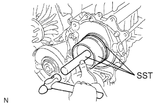
Using SST, remove the oil seal.
- SST
- 09308-10010
- 09950-40011 ( 09957-04010 )
- 09950-60010 ( 09951-00350 )
-
Apply MP grease to the lip of a new oil seal.
-
Using SST and a hammer, tap in the oil seal until its surface is flush with the timing gear cover edge.
- SST
- 09214-76011
-
-
-
INSTALL TIMING GEAR CASE OIL SEAL
Tech Tips
There are 2 methods to remove the oil seal.
-
If the timing gear cover is removed from the cylinder block:
-
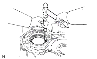
Using a screwdriver and hammer, tap out the oil seal.
-
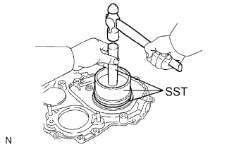
Using SST and a hammer, tap in a new oil seal until its surface is flush with the timing gear cover edge.
- SST
- 09223-15020
- 09502-12010
- 09950-70010 ( 09951-07100 )
-
Apply MP grease to the lip of the oil seal.
-
-
If the timing gear cover is installed to the cylinder block:
-
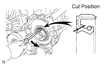
Using a knife, cut through the lip of the oil seal.
-
Using a screwdriver, pry out the oil seal.
Note
Be careful not to damage the crankshaft.
-
Apply MP grease to the lip of the oil seal.
-
Using SST and a hammer, tap in a new oil seal until its surface is flush with the timing gear cover edge.
- SST
- 09223-15020
- 09502-12010
- 09950-70010 ( 09951-07100 )
-
-
-
INSTALL TIMING GEAR COVER
-
Remove any old seal packing (FIPG material).
-
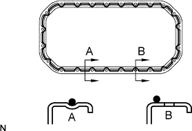
Text in Illustration *A w/ DPF *B w/o DPF *1 Seal Packing Apply seal packing to the timing gear cover as shown in the illustration.
Seal packing Toyota Genuine Seal Packing Black, Three Bond 1207B or equivalent Standard seal diameter 4 mm (0.16 in.) Note
Install the timing gear cover within 3 minutes and tighten bolts within 15 minutes of applying seal packing.
-
w/ DPF:
Install 3 new O-rings to the timing gear case.
-
Text in Illustration *1 New O-Ring w/o DPF:
Install a new O-ring to the timing gear case.
-
Install the timing gear cover with the 14 bolts and 2 nuts.
- Torque:
- 13 N*m { 133 kgf*cm, 10 ft.*lbf }
-
-
INSTALL OIL STRAINER SUB-ASSEMBLY
-
Install a new gasket and the oil strainer with the 2 bolts and 2 nuts.
- Torque:
- 8.0 N*m { 82 kgf*cm, 71 in.*lbf }
-
-
INSTALL OIL PAN SUB-ASSEMBLY
-
Remove any old seal packing (FIPG material).
-
Apply seal packing to the oil pan as shown in the illustration.
Seal packing Toyota Genuine Seal Packing Black, Three Bond 1207B or equivalent Standard seal diameter 4.0 mm (0.16 in.) Note
Install the oil pan within 3 minutes and tighten the bolts within 15 minutes of applying seal packing.
-
w/o DPF:
Apply seal packing to the cylinder block stiffening plate as shown in the illustration.
Seal packing Toyota Genuine Seal Packing Black, Three Bond 1207B or equivalent Standard seal diameter 4.0 mm (0.16 in.) Note
Install the cylinder block stiffening plate within 3 minutes and tighten the bolts within 15 minutes of applying seal packing.
-
w/ DPF:
Install the oil pan with the 22 bolts and 2 nuts.
- Torque:
- 12 N*m { 122 kgf*cm, 9 ft.*lbf }
-
w/o DPF:
Install the cylinder block stiffening plate and oil pan with the 22 bolts and 2 nuts.
- Torque:
- 12 N*m { 122 kgf*cm, 9 ft.*lbf }
-
-
INSTALL CRANKSHAFT PULLEY
-
Align the keyway of the pulley with the key located on the crankshaft, and then slide the pulley into place to install it.
-
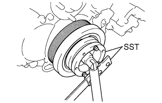
Using SST, install the pulley bolt.
- SST
- 09213-58014
- 09330-00021
- Torque:
- 365 N*m { 3722 kgf*cm, 269 ft.*lbf }
-
-
INSTALL WATER PUMP ASSEMBLY
-
Install a new gasket and the water pump with the 5 bolts and 2 nuts.
- Torque:
- 13 N*m { 133 kgf*cm, 10 ft.*lbf }
-
-
INSTALL NO. 2 TIMING BELT COVER
-
Apply seal packing (FIPG) to the areas shown in the illustration.
Seal Packing Toyota Genuine Seal Packing Black, Three Bond 1207B or equivalent Note
After applying FIPG, install the No. 2 timing belt cover within 3 minutes and tighten the bolts and nut within 15 minutes.
-
Clean the bolts and their holes.
-
Apply adhesive to 2 or 3 threads at the end of 4 bolts.
Adhesive Toyota Genuine Adhesive 1324, Three Bond 1324 or equivalent -
Install the No. 2 timing belt cover with the 4 bolts and nut.
- Torque:
- 10 N*m { 102 kgf*cm, 7 ft.*lbf }
-
-
INSTALL CAMSHAFT TIMING PULLEY
-
Install the camshaft timing pulley.
-
Install the bolt of the camshaft timing pulley while holding the camshaft with a wrench.
- Torque:
- 98 N*m { 1000 kgf*cm, 72 ft.*lbf }
-
-
INSTALL INJECTOR ASSEMBLY
-
INSTALL FUEL SUPPLY PUMP ASSEMBLY
-
INSTALL COMMON RAIL ASSEMBLY
-
INSTALL EGR COOLER WITH NO. 2 EGR VALVE ASSEMBLY
-
INSTALL ELECTRIC EGR CONTROL VALVE ASSEMBLY
-
INSTALL DIESEL THROTTLE BODY ASSEMBLY
-
INSTALL OIL PRESSURE SWITCHING VALVE ASSEMBLY
-
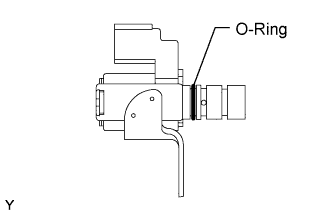
Apply a light coat of engine oil to the O-ring of the oil pressure switching valve.
-
Install the oil pressure switching valve with the bolt.
- Torque:
- 10 N*m { 102 kgf*cm, 7 ft.*lbf }
Note
Make sure that the O-ring is not cracked or jammed when installing the oil pressure switching valve.
-
Connect the oil pressure switching valve connector.
-
-
INSTALL CAMSHAFT POSITION SENSOR
-
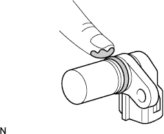
Apply a light coat of engine oil to the O-ring of the camshaft position sensor.
-
Install the camshaft position sensor with the bolt.
- Torque:
- 8.5 N*m { 87 kgf*cm, 75 in.*lbf }
Note
Do not crack or jam the O-ring when installing the camshaft position sensor.
-
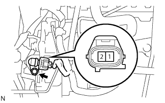
Connect the camshaft position sensor connector.
-
-
INSTALL CRANKSHAFT POSITION SENSOR
-
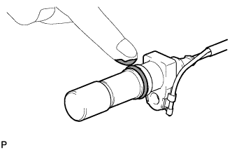
Apply a light coat of engine oil to the O-ring of the crankshaft position sensor.
-
TYPE A:
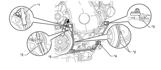
Text in Illustration *1 Clamp *2 Protrusion *3 Wire Harness Clamp (A) *4 Wire Harness Clamp (B) *5 Wire Harness Clamp (C) - -
-
Install the wire harness clamp (A) to the crankshaft position sensor connector.
-
Install the crankshaft position sensor with the bolt.
- Torque:
- 8.5 N*m { 87 kgf*cm, 75 in.*lbf }
Note
Make sure that the O-ring is not damaged or does not jump out of position during installation.
-
Install a new clamp.
Note
-
Make sure that no portion of the clamp remains in the clamp installation hole. If there is any portion of the clamp remaining, remove it.
-
Make sure the crankshaft position sensor wire harness is installed in the position shown in the illustration.
-
-
Attach the crankshaft position sensor connector to the No. 1 vacuum transmitting pipe.
-
Connect the crankshaft position sensor connector.
-
Attach the 2 wire harness clamps (B, C).
-
-
TYPE B:
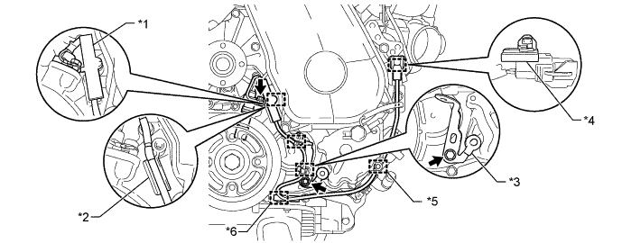
Text in Illustration *1 Clamp *2 Protrusion *3 Bracket (Clamp) *4 Wire Harness Clamp (A) *5 Wire Harness Clamp (B) *6 Wire Harness Clamp (C)
-
Install the wire harness clamp (A) to the crankshaft position sensor connector.
-
Install the crankshaft position sensor with the bolt.
- Torque:
- 8.5 N*m { 87 kgf*cm, 75 in.*lbf }
Note
Make sure that the O-ring is not damaged or does not jump out of position during installation.
-
Install the bracket (clamp) with the bolt.
- Torque:
- 13 N*m { 132 kgf*cm, 9.5 ft.*lbf }
-
Install a new clamp.
Note
-
Make sure that no portion of the clamp remains in the clamp installation hole. If there is any portion of the clamp remaining, remove it.
-
Make sure the crankshaft position sensor wire harness is installed in the position shown in the illustration.
-
-
Attach the crankshaft position sensor connector to the No. 1 vacuum transmitting pipe.
-
Connect the crankshaft position sensor connector.
-
Attach the 2 wire harness clamps (B, C).
-
Attach the 2 wire harness clamps to the bracket (clamp).
-
-
-
INSTALL NO. 1 TIMING BELT IDLER SUB-ASSEMBLY
-
Using a 10 mm hexagon wrench, install a new washer and the No. 1 timing belt idler with the bolt.
- Torque:
- 35 N*m { 357 kgf*cm, 26 ft.*lbf }
-
-
INSTALL TIMING BELT
-
INSTALL VACUUM PUMP ASSEMBLY
-
Install 2 new O-rings and the vacuum pump with the 2 nuts.
- Torque:
- 21 N*m { 210 kgf*cm, 15 ft.*lbf }
-
-
INSTALL VANE PUMP ASSEMBLY
-
Install a new vane pump O-ring to the vane pump assembly.
-
Install the vane pump assembly with the 2 nuts.
- Torque:
- 39 N*m { 398 kgf*cm, 29 ft.*lbf }
Note
Make sure that the vane pump O-ring is not caught between other parts.
-
-
REMOVE ENGINE STAND
-
Remove the engine from the engine stand.
-
-
INSTALL ENGINE ASSEMBLY